Attachment Feature Creation - Ribs
AIM :
To create the rib for the Centre Console Coin Holder.
OBJECTIVE :
- To make sure that the model meets the design rules for rib creation.
- To create the Tooling axis using bisecting method.
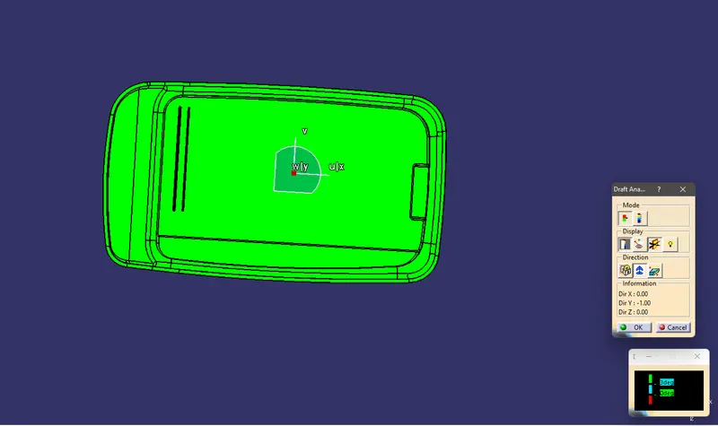
- To perform Draft analysis on the component.
RIB :
- Rib is a feature which provides stiffness and strength to molded parts.
- They are thin extensions that run perpendicular from a wall or plane.
- They provide these features without increasinbg the overall thickness.
- If the wall is too thick, warping and sinking can result so that the entire design may need to be rejected.
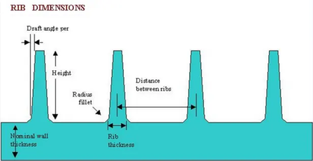
- Taller Ribs provide great support, Rib height might approximately taken as 5 times the base thickness.
- For wall thickness less than 1 mm, rib thickness is same as the wall thickness.
- A Draft of 0.5 degrees per side is the minimum limit.
- Rib thickess can be taken as 0.4 times the base thickness.
- Minimum thickness at the rib tip is 0.75 mm.
- Optimum rib fillet radius can be taken as 0.25 mm which is optional.
PROCEDURE :
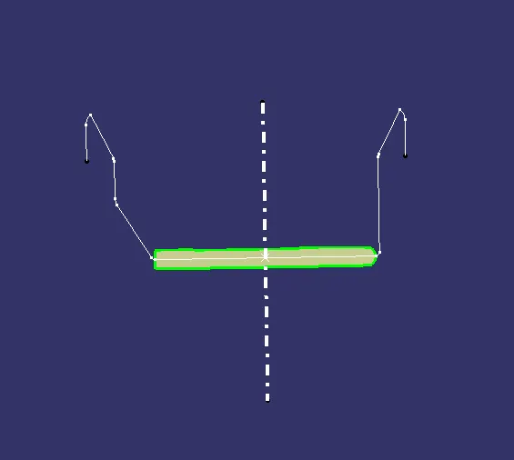
Creating Tooling Axis
- Initially a base surface was extracted from the Class A to create a center point.
- An axis system was created upon this point.
- The Intersect feature was used to obtain a boundary of the Class A intersecting at the mid plane.
- Once the check for the discrepencies in the boundary is done, the Tooling axis was created from thr mid-point.
Creating Rib feature
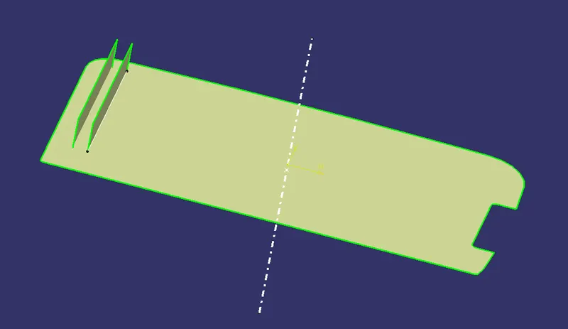
- Ibitiallt the base surface from the plastic component was extracted.
- A sketch for the rib was created on the surface.
- An additional sktech was also created through offset for another rib.
- These sketches were extruded and thickened using Thick Sucface command.
- The necessary drafts and fillets were provided to the ribs.
Draft Analysis
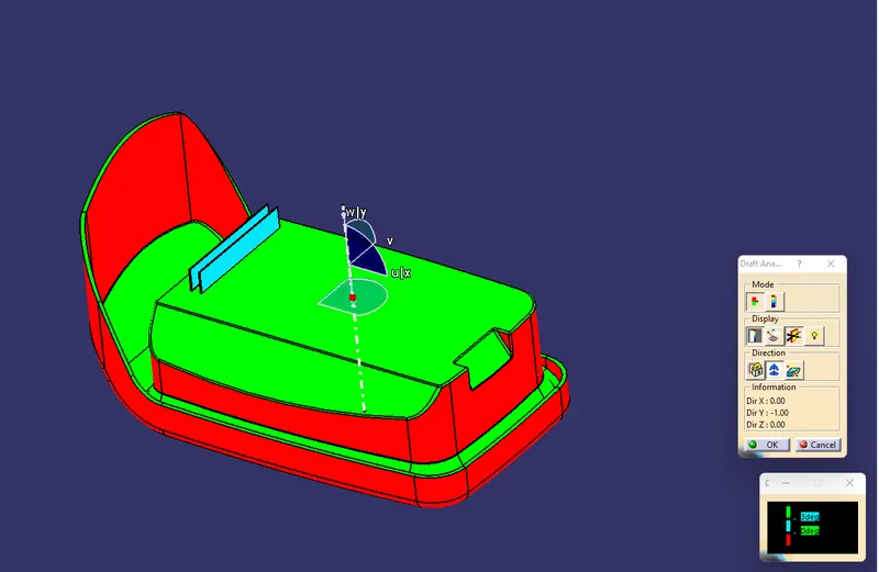
- The Drafting analysis was performed using the Feature Draft Analysis command.
- Using this command the compass was set on the main tooling axis and the Draft angle was changed to 3 degree.
MODEL RESULTS :
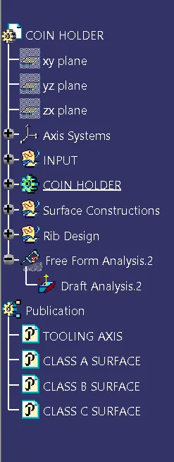
Feature tree
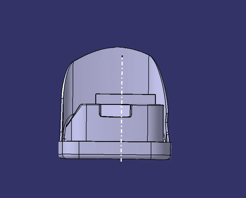
Front view
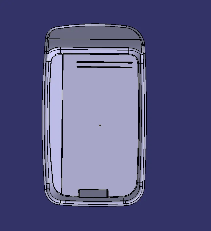
Top view
Side view
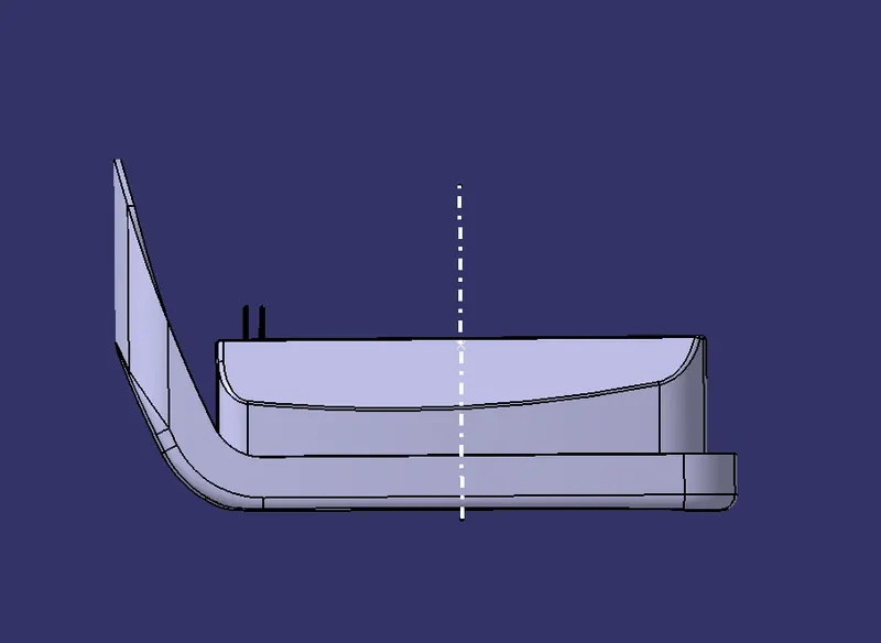
Isometric view
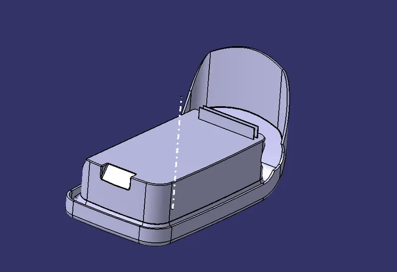
CONCLUSION :
- The creation of Tooling axis and Draft analysis were performed.
- The Rib features were created.
- The necessary screenshots and files were attached.