3D Finishing
AIM :
To study about the various design aspects regarding BIW fixtures.
OBJECTIVE :
- To explain about 3D finishing process.
- To discuss about the points need to be taken care of while finishing the design.
- To explain about the Rough locators.
- To discuss about the points need to be considered while designing a Rough locator.
- To brief about the Gun study process.
- To discuss about the points need to be considered during a Gun study process.
- To explain about Pneumatic routing.
- To explain about the solenoid valve.
- To explain about the valve bank.
- To explain about Sensor and its application in Aotomation.
- To dicuss about the types of the sensor.
- To discuss about the fundamental points that need to consider while designing or selection of sensor.
1. 3D finishing process
- Hole concentricity & hole sizes.
- Machining area.
- Nominality.
- Holes colouring standard.
- Pneumatic lay-outing.
- Gaps checking.
- Fasteners implementation.
- Mylars Splitting as per panel profile.
- Proper renaming of parts/assemblies as per the standard.
Once the 3D finishing is done, the entire assembly is further sent for simulation and 2D detailing.
2. Finishing the design process
The following aspects must be checked while finishing the design process,
Hole concentricity & hole sizes
- Hole concentricity and size of the component must be checked in order to make the assembly process easier.
Machining area
- The Machining area must be highlighted using a proper colour code.
Nominality
- Nominal dimensions must be used in the components in order to ensure proper fit in the assembly.
Holes colouring standard
- Standard colour code must be followed according to the customer requirements.
- Simple hole - Violet
- Threaded hole - Yellow
- Machined area - Cream
- Dowel hole - Cyan
Pneumatic lay-outing
- It is the collective presence of various pneumatic pipes which work as an inlet to the pneumatic cylinder.
Gaps checking
- Proper gaps between components must be ensured in order to avoid any damage to the adjacent components.
Fasteners implementation
- Fastners must be implemented in the assembly as per the requirements.
Mylars Splitting as per panel profile
- Mylar splitting must be done with the given car panel.
- It must be ensured before the end of the design process.
Proper renaming of parts/assemblies as per the standard
- Proper renaming of part mus be done as per the standard for easy identification and to avoid confusion.
3. Rough locators
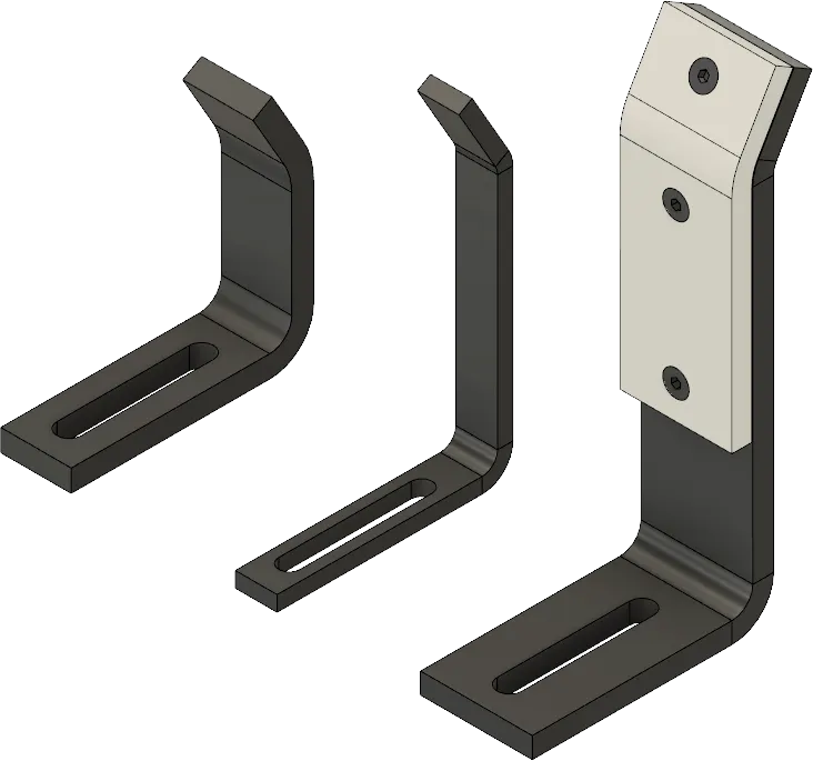
Rough locators are used to help locate workpieces in the automation process.
Locating refers to the desired location where you want the workpiece to be when it is getting worked on either by a person, team, or robot.
It is a device to establish and maintain position of a part in a jig or fixture.
It can also be called as fool proofing method as the rough locators are set according to the angle of their respective panels.
Thus the parts can be loaded in a defined direction and orientation.
The accuracy of the part locations are very crucial as they affect the final assembly.
4. Designing a Rough locator
The points need to be considered while designing a Rough locator are,
- It is used to guide the conponent to place it properly.
- It is generally placed at the edges.
- It must have an entry angle of 30 to 45 degree.
- It must guide the component at a distance of 10 to 15 mm before the engagement
- It is mounted on the base with slots for easy positioning.
- It must be placed at the same angle as the car panel.
- The slots must be in the direction of guiding the car part.
- These locators must be placed within two slots for making the mounting process simpler.
5. Gun study process
Apart from safety, clean and strong welds are an important part of a vehicle as it improves its appearance and reliability. Automotive welding requires highly skilled welders to perform various welds, to fix cracked vehicle panels, damaged fenders, welding exhaust on cars or rusted metal, etc.
- In BIW the complicated steel-structure including 300mm to 500mm sheets with complex shape and are assembled by means of welding.
- The initial step taken before starting the design of welding fixture is to arrive at the spot weld locations.
- The location and orientation of other critical units of the fixture including clamps, locators etc., are decided based on the weld spot distribution.
- These locations must be altered if it afects the travel of the weld gun.
- Thus this is an important aspect in the finishing of the Design process.
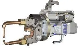
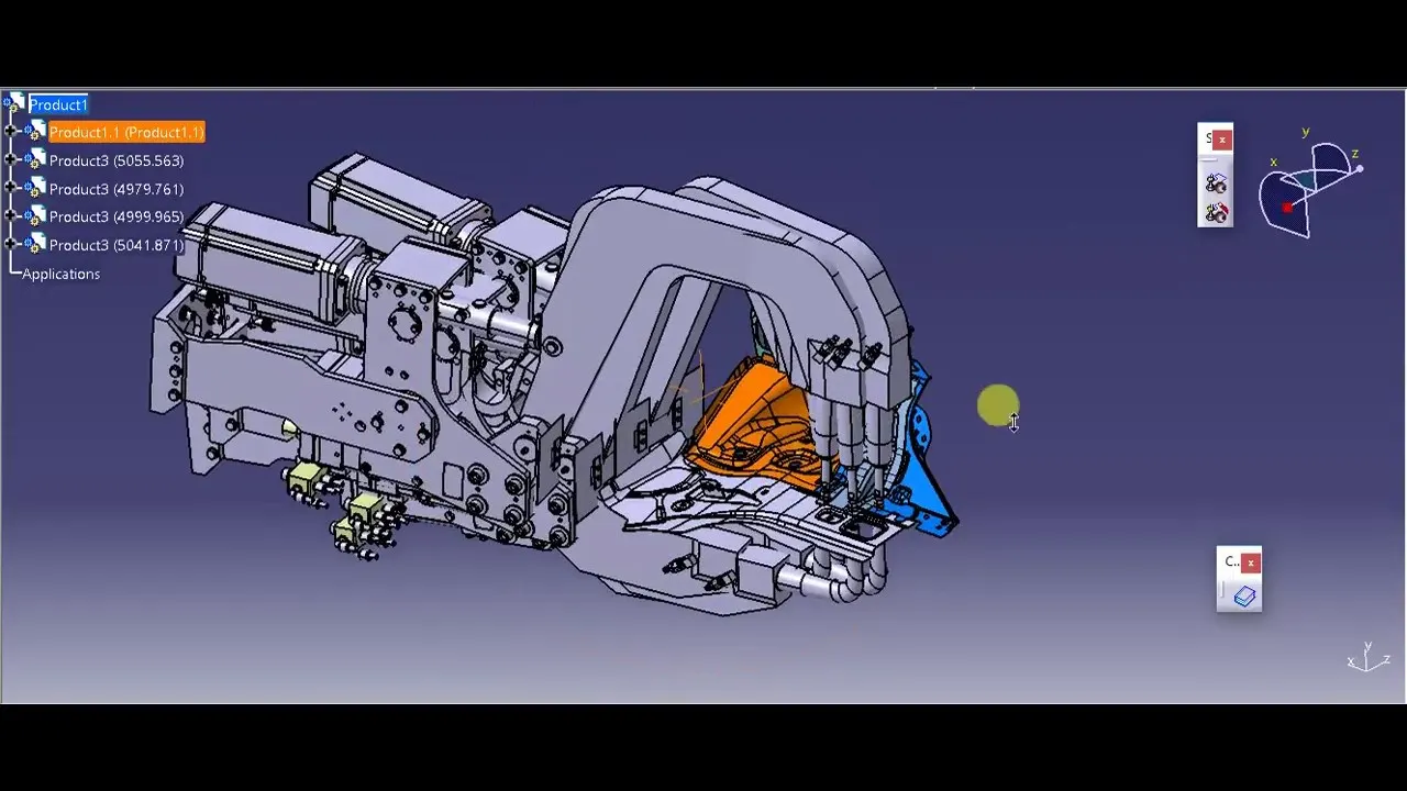
- In the weld gun study the gun which is going to be used while spot welding is checked over the panel by using tI software.
- The fixture is designed for the car panel to hold it on the position, the weld gun position is checked ovel predefined spot weld points .
- If the weld gun fall intescets with the fixtureto the fixture, the redesigning of that unit or the repositioning of that unit is done.
- It is ensured that there is no intersection between the various units and the weld gun.
6. Various aspects of Gun study process
The various aspects considered using the gun study are,
- The axis of weld spot along welding direction must behnormal to the weld surface.
- The no. of weld spots for the panel and the time required to spot the each weld determine the total time required to complete all the weld spots.
- If we have one or more Device models and we want to program; the behavior of each model in the work cell can be simulated over time. Instructions for each device are coded by giving Sequences.
- The sequence defines the motion, manipulation and action of the devices.
- Based on the distance of each tag point from home position, motion type, speed and acceleration - one can obtain cycle time for each device assigned with sequences. This way robot cycle time is precisely calculated.
- After sequencing all the devices, a simulation is run with "collision check" ON and made sure that the welding operation is collision free.
7. Pneumatic routing
Pneumatic System is a system operated with Air.
It is anOpen loop system.
It is generally used for low pressure and delivers less force compared to hydraulic system.
It is cheaper compared to hydraulic for basic cost but compressor running cost is more.
Pneumatic system is mostly preferred over hydraulic system in BIW welding fixture.
All toggle clamp, pin cylinder, slides are operated via pneumatic systems.
Generally cylinder are designed to operate max pressure 12-13 bar.
As it expensive and difficult to maintain 10-12 bar in shop floor it is preferred to design pneumatic systems at 6 bar pressure
Proper Pneumatic lay-outing or routing is very much important to be shown in design, as it helps in describing the best possible way to keep all pneumatic pipes neat & away from welding spatters which can cause wear or tear of pneumatic pipes.
In pneumatic lay-outing all pipes from cylinders are shown connected to valve banks and passes through a safety box like structure.
Various major suppliers for pneumatics items are SMC, Teunkers, Festo, CKD etc.
Certain guidelines are involved in pneumatic routing which include,
- Leave fitting joints as accessible as possible. Inaccessible joints are difficult and time-consuming to assemble, tighten and service.
- Use software tools to make labor-intensive calculations such as pressure drop.
- Employ U-bends to allow for line contraction and expansion.
- Include offset bends to allow for motion under load, regardless of how ‘rigid’ the system seems.
- Favor bends rather than straight tube lines, because a straight line tube assembly with no bends, like the example of the test stand mentioned above, can cause joint stain which may lead to leaking.
- Make sure routing design allows room for assembly of any connections required.
- Minimize pressure drop by getting around obstructions with as few 90° bends as possible. One 90° bend has more pressure loss than two 45° bends.
- Route lines around rather than over areas that require regular access or maintenance.
- Design routing with clamping in mind. Appropriate design leads logically to proper clamping. Often, it’s possible to clamp several lines together.
- Keep troubleshooting and maintenance in mind: focus on logical design and avoid crossed lines.
- Design the tube line routing to reduce likelihood of users standing or climbing on plumbing.
8. Solenoid valve
The definition of a solenoid valve is an electro-mechanical valve that is commonly employed to control the flow of liquid or gas. There are various solenoid valve types, but the main variants are either pilot operated or direct acting. Pilot operated valves, the most widely used, utilise system line pressure to open and close the main orifice in the valve body.
While Direct operated solenoid valves directly open or close the main valve orifice, which is the only flow path in the valve. They are used in systems requiring low flow capacities or applications with low pressure differential across the valve orifice.
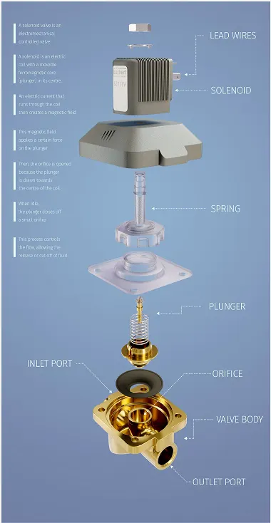
A solenoid valve works is by controlling the flow of liquids or gases in a positive, fully-closed or fully-open mode. They are often used to replace manual valves or for remote control. Solenoid valve function involves either opening or closing an orifice in a valve body, which either allows or prevents flow through the valve. A plunger opens or closes the orifice by raising or lowering within a sleeve tube by energising the coil.
Solenoid valves consist of a coil, plunger and sleeve assembly. In normally closed valves, a plunger return spring holds the plunger against the orifice and prevents flow. Once the solenoid coil is energised, the resultant magnetic field raises the plunger, enabling flow. When the solenoid coil is energised in a normally open valve, the plunger seals off the orifice, which in turn prevents flow.
Common domestic and industrial solenoid valve applications include
- Refrigeration systems use solenoid valves to reverse the flow of refrigerants. This helps in cooling during summer and heating during winter.
- Irrigation systems use solenoid valves with automatic control.
- Dishwashers and washing machines use solenoid valves to control the flow of water.
- Air conditioning systems use solenoid valves to control air pressure.
- Solenoid valves are used in automatic locking systems for door locks.
- Medical and dental equipment use solenoid valve to control the flow, direction and pressure of the fluid.
- Water tanks use solenoid valves to control the inflow or outflow of water, often in combination with a float switch.
- Car washes to control the water and soap flow.
- Industrial cleaning equipment
9. Valve bank
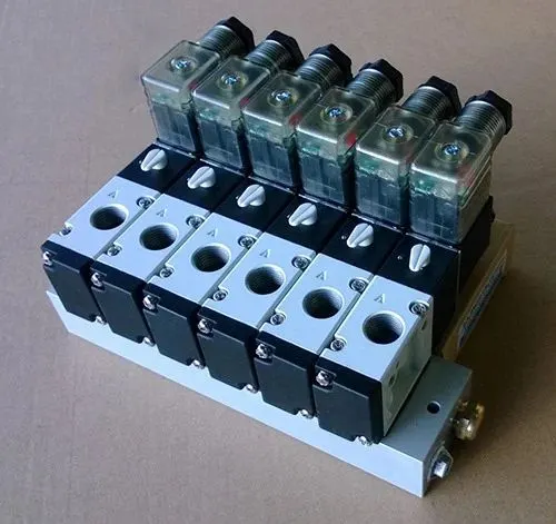
A solenoid valve manifold is similar to a solenoid valve in that it controls the flow of liquids or gasses. This product differs in that the manifold connects multiple solenoid valves together in a valve bank. Each of the solenoid valves contains the necessary coil windings, spring and plunger that stops and directs the flow of media through the manifold.
Since a solenoid valve manifold uses multiple solenoid valves in one valve bank, the manifold can direct the flow of flow of liquid or gas in multiple directions and destinations.. Solenoid valves generally are less expensive than individual solenoid valves and reduce the potential for leaks in the system.
Solenoid valves are used for a variety of applications to control the flow liquids and gasses in a huge variety of applications including all types of transportation products, medical products, beverage dispensing equipment and HVAC products. Solenoid valves safely and effectively control the follow of liquids and gasses, therefore allowing products to operate at the optimal capacity. Although a single solenoid valve can be used for certain applications, at times, more than one valve needs to be used to properly control the flow of the desired liquid or gas. This is when solenoid valve manifolds become beneficial.
10. Sensor and its application in Automation
A sensor is a device that detects and responds to some type of input from the physical environment.
The specific input could be light, heat, motion, moisture, pressure, or any one of a great number of other environmental phenomena.
Each component must be sensed in order to minimize the errors involved.
Sensors can be used to determine the extrinsic properties of objects such as position, distance, and proximity. Sensors also can be used to evaluate intrinsic characteristics like temperature and color. Design engineers can choose among a wide variety of sensor systems. Here, we review just a few of the most common.
Presence/absence sensors use non-contact technology to detect the presence or absence of the object of interest and report the results to the controller or drive using an electrical signal. Because these sensors are noncontact, they minimize damage or wear to the device under test and to the sensor itself.
The environmental conditions of the application drive the specific technology choice. Key factors to consider include temperature, ambient light, moisture, airborne particulates, shock and vibration, and other contaminants. In addition, some sensor technologies require a metal target in order to operate. The Motion Solutions sales team is well-versed in our sensor portfolio. They can help you not only find the appropriate technology but a specific device that will achieve the accuracy, resolution, lifetime, and cost target that your application requires.
Sensors in Automation
- In industrial automation, sensors play a vital role in making production intelligent and automated.
- These allow people to monitor, analyze, and process various changes that occur on the industrial manufacturing site, such as changes in temperature, motion, pressure, altitude, external, and security.
- Almost every process or environmental condition has a suitable sensor type.
- The smart sensor integrates signal conditioning, MEMS technology, and firmware, so as to meet the easy-to-use and low-cost perception needs of industrial design engineers, and greatly reduce the development burden of design engineers.
11. Types of the sensor
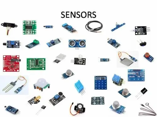
The following are the various types of sensors most commonly used in automation:
- Temperature Sensors
- Pressure sensors
- Level sensors
- Infrared sensors
- Proximity sensors
- Smoke sensors
- Optical Sensors
- MEMS Sensors
- Ultrasonic Sensors
- Colour Sensors
- Humidity Sensors
- Heartbeat Sensor
As the entrance to the information collection, sensors are the “heart” of the Internet of Things, smart industries, and smart devices. The realization and development of the Industrial Internet are inseparable from the wide application of sensors and technological innovation. However, on the other hand, the Industrial Internet has also brought a huge market for the development of sensors. Industrial Internet and sensor development can be described as complementary.
12. Designing or Selection of a Sensor
The fundamental points that need to consider while designing or selection of sensor are,
- Sensor unit is unit designed to sense the the car panel by using Electrical sensors.
- The signal from sensors will be fed to the PLC and durther process will be executed with this signal.
- Sensos are used in the confirming their is panel/component present or not.
- It should help to avoid human error.
- Basially sensors should be equal numers as compared to the numbers of panels in a assembly.
- In general these sensors must be installed as a 3 direction adjustable unit.
- Sensors should take care of the safety functions in the assembly.
- Typically Proximity, LASER, Photoelectric Sensors are used in fixtures..
CONCLUSION :
All the given objectives were satisfied with atmost perfection.
The images were attached wherever necessary