Advanced Sheet Metal Design Using NX Cad-Box Assembly
AIM :
To perform the given Sheet Metal design using NX CAD
OBJECTIVE :
- To design a Box Assembly in NX CAD
ABOUT :
Sheet Metal :
Sheet metal is metal formed by an industrial process into thin, flat pieces. Sheet metal is one of the fundamental forms used in metalworking, and it can be cut and bent into a variety of shapes. Countless everyday objects are fabricated from sheet metal. Thicknesses can vary significantly; extremely thin sheets are considered foil or leaf, and pieces thicker than 6 mm (0.25 in) are considered plate steel or "structural steel".
Sheet metal is used in automobile and truck (lorry) bodies, airplane fuselages and wings, medical tables, roofs for buildings (architecture), and many other applications. Sheet metal of iron and other materials with high magnetic permeability, also known as laminated steel cores, has applications in transformers and electric machines.
Historically, an important use of sheet metal was in plate armor worn by cavalry, and sheet metal continues to have many decorative uses, including in horse tack.
Sheet metal is available in flat pieces or coiled strips. The coils are formed by running a continuous sheet of metal through a roll slitter.
DESIGN METHODOLOGY :
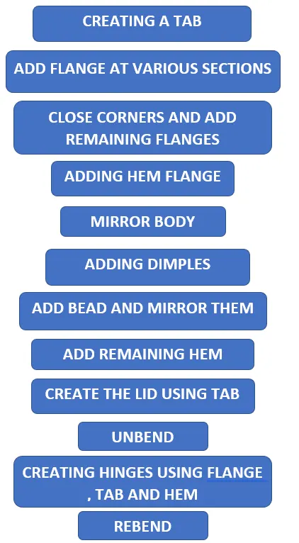
DESCRIPTION :
Sketch : The 2D representation of the given profiles are obtained using sketch.
Tab : This feature is used to create a base with some thickness.
Flange : It is used to create an extended part from the sheet metal at required angles.
Closed corner : It closes a corner where two adjacent flanges meet by extending the bends and flanges.
Hem Flange : It is used to fold or roll the edge of the sheet metal flange over itself to provide stiffness.
Mirror Body : It is used to mirror an entire body based on references.
Dimple : It is used to embed a profile onto the sheet metal with certain depth either in or out.
Bead : This feature is used to lift the material based on a certain profile on the sheetmetal which strengthens the sheet metal.
Mirror feature : It is used to mirror any feature or sketch based on references.
Unbend : It is used to unbend the entire sheet metal into a flat surface.
Rebend : It is used to bend all the features of a sheet metal after an unbend.
MODEL :
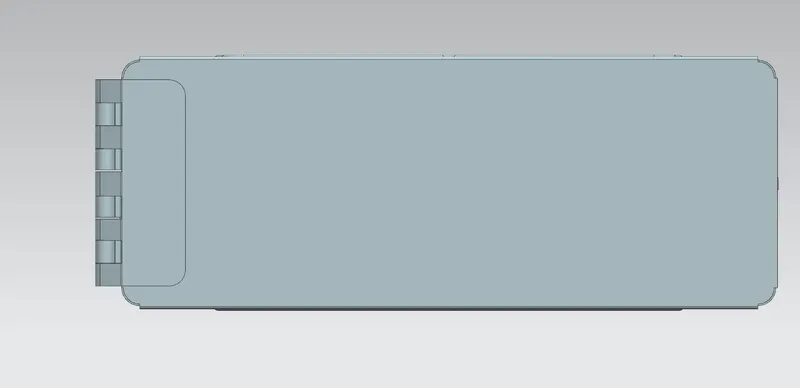
Top view
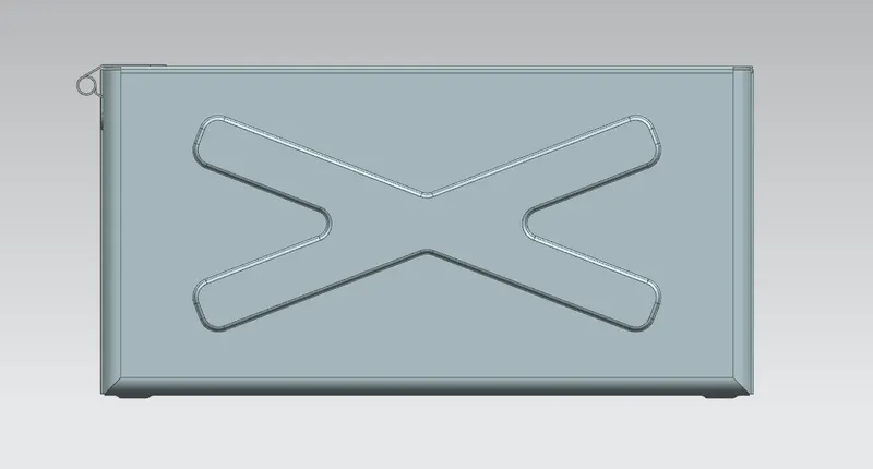
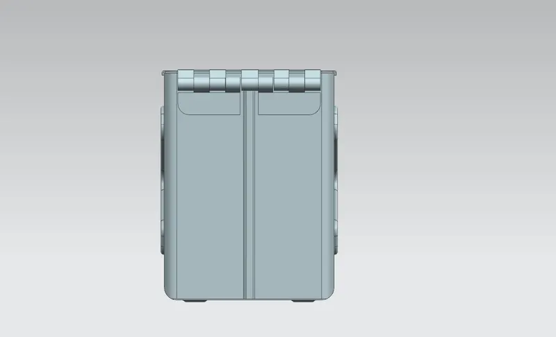
Front view
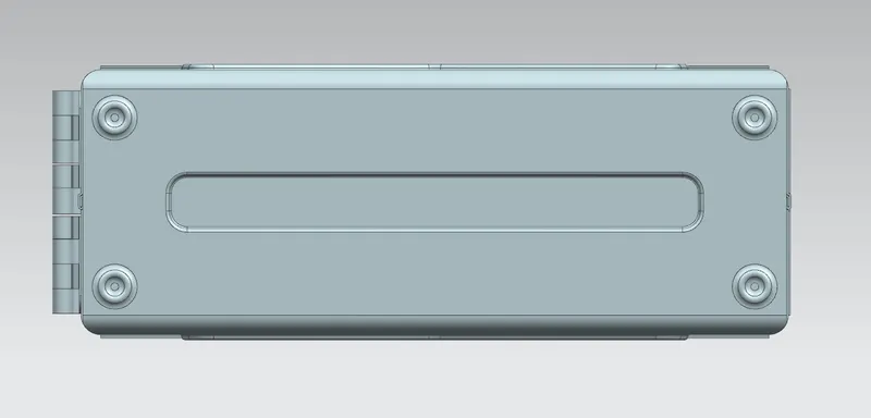
Bottom view
Side view
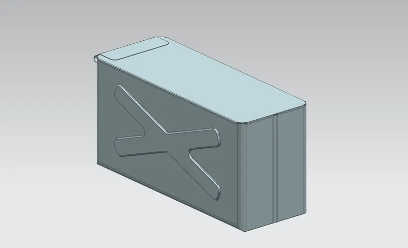
Isometric view
CONCLUSION :
- The model was designed as per the given dimensions.
- Images were attached representing various views.
- The model file was attached