Project-1: Powertrain for aircraft in runways
AIM :
To perform the various operations corresponding to an Electric vehicle inorder to fulfill the required objectives that were provided.
OBJECTIVE :
- To list out the total weight of various types of aircrafts.
- To state the difference between ground speed and air speed.
- To know about moving the aircraft on ground at the Airport.
- To know how an aircraft is pushed to runway when its ready to take off.
- To learn about take off power, tyre design, rolling resistance, tyre pressure, brake forces when landing.
- To calculate the force and power required to push / pull an aircraft by a towing vehicle.
- To design an electric powertrain to fulfill aircraft towing application.
1. Weight of various aircrafts
An aircraft is a vehicle that is able to fly by gaining support from the air. It counters the force of gravity by using either static lift or by using the dynamic lift of an airfoil, or in a few cases the downward thrust from jet engines.
The various types of weights in Aircraft are,
- Standard Empty Weight
- Basic Empty Weight
- Useful Load
- Payload
- Maximum Ramp Weight
- Maximum Take-off Weight
- Minimum Flight Weight
- Maximum Landing Weight
- Aircraft Gross Weight
Aircraft Gross Weight
The aircraft gross weight is the total aircraft weight at any moment during the flight or ground operation. An aircraft's gross weight will decrease during a flight due to fuel and oil consumption. An aircraft's gross weight may also vary during a flight due to payload dropping or in-flight refuelling.
List of Airlines by maximum take-off weight
| Type | MTOW [kg] | MLW [tonnes] | TOR [m] | LR [m] | ICAO category | FAA category |
|---|---|---|---|---|---|---|
| Antonov An-225 | 640,000 | 591.7 | 3500 | Heavy | Super | |
| Scaled Composites Model 351 Stratolaunch | 589,670 | 3660 | Heavy | Super | ||
| Airbus A380-800 | 575,000 | 394 | 3100 | 1930 | Super | Super |
| Boeing 747-8F | 447,700 | 346.091 | 3100 | 1800 | Heavy | Heavy |
| Boeing 747-8 | 443,613 | 306.175 | 3100 | Heavy | Heavy | |
| Boeing 747-400ER | 412,770 | 295.742 | 3090 | Heavy | Heavy | |
| Antonov An-124-100M | 405,060 | 330 | 2520 | 900 | Heavy | Heavy |
| Boeing 747-400 | 396,900 | 295.742 | 3018 | 2179 | Heavy | Heavy |
| Lockheed C-5 Galaxy | 381,000 | 288.417 | 2530 | 1494 | Heavy | Heavy |
| Boeing 747-200 | 377,840 | 285.700 | 3338 | 2109 | Heavy | Heavy |
| Boeing 747-300 | 377,840 | 260.320 | 3222 | 1905 | Heavy | Heavy |
| Airbus A340-500 | 371,950 | 240 | 3050 | 2010 | Heavy | Heavy |
| Airbus A340-600 | 367,400 | 256 | 3100 | 2100 | Heavy | Heavy |
| Boeing 777F | 347,800 | 260.816 | 2830 | Heavy | Heavy | |
| Boeing 777-300ER | 351,800 | 251.29 | 3100 | Heavy | Heavy | |
| Boeing 777-200LR | 347,450 | 223.168 | 3000 | Heavy | Heavy | |
| Boeing 747-100 | 340,200 | 265.300 | Heavy | Heavy | ||
| Airbus A350-1000 | 308,000 | 233.5 | Heavy | Heavy | ||
| Boeing 777-300 | 299,370 | 237.683 | 3380 | Heavy | Heavy | |
| Boeing 777-200ER | 297,550 | 213.00 | 3380 | 1550 | Heavy | Heavy |
| Airbus A340-300 | 276,700 | 190 | 3000 | 1926 | Heavy | Heavy |
| McDonnell Douglas MD-11 | 273,300 | 185 | 2990 | 1890 | Heavy | Heavy |
| Airbus A350-900 | 270,000 | 175 | 2670 | 1860 | Heavy | Heavy |
| Ilyushin Il-96M | 270,000 | 195.04 | 3115 | 2118 | Heavy | Heavy |
| McDonnell Douglas DC-10 | 256,280 | 183 | 2990 | 1890 | Heavy | Heavy |
| Boeing 787-9 | 254,000 | 192.777 | 2900 | Heavy | Heavy | |
| Boeing 787-10 | 254,000 | 201.849 | Heavy | Heavy |
2. Ground & Air speed of an Aircraft
Wind Speed :
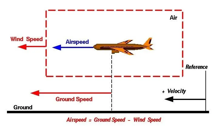
For a reference point picked on the ground, the air moves relative to the reference point at the wind speed. Notice that the wind speed is a vector quantity and has both a magnitude and a direction. Direction is important. A 20 mph wind from the west is different from a 20 mph wind from the east. The wind has components in all three primary directions (north-south, east-west, and up-down). In this figure, we are considering only velocities along the aircraft's flight path. A positive velocity is defined to be in the direction of the aircraft's motion. We are neglecting cross winds, which occur perpendicular to the flight path but parallel to the ground, and updrafts and downdrafts, which occur perpendicular to the ground.
Air Speed :
The important quantity in the generation of lift is the relative velocity between the object and the air, which is called the airspeed. Airspeed cannot be directly measured from a ground position, but must be computed from the ground speed and the wind speed. Airspeed is the vector difference between the ground speed and the wind speed.
Airspeed = Ground Speed - Wind Speed
On a perfectly still day, the airspeed is equal to the ground speed. But if the wind is blowing in the same direction that the aircraft is moving, the airspeed will be less than the ground speed.
Ground Speed :
For a reference point picked on the ground, the aircraft moves relative to the reference point at the ground speed. Ground speed is also a vector quantity so a comparison of the ground speed to the wind speed must be done according to rules for vector comparisons.
3. Moving the aircraft on ground at the Airport
- Pushing an Aircraft using the aircraft's engine power is a highly fuel consuming and a noisy process overall.
- It is hazardous for the personnel working near the aircraft.
- Many aircrafts has the ability to move themselves forward and even backward using reverse thrust which thereby results in a jet blast and can cause damage to the terminal building equipment.
- When the Engine is close to the ground, it may blow the sand and dust and eventually ends up sucking them into the engine which causes damage to the engine.
- Thus a pushback is preferred to move the aricraft away from the gate.
- After the aircraft is present at a safe distance from the terminal, it uses its own engine power for the rest of the taxing process.
4. Aircraft pushback towards runway
In aviation, pushback is an airport procedure during which an aircraft is pushed backwards away from an airport gate by external power. Pushbacks are carried out by special, low-profile vehicles called pushback tractors or tugs.
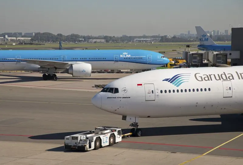
Although many aircraft are capable of moving themselves backwards on the ground using reverse thrust , the resulting jet blast or prop wash might cause damage to the terminal building or equipment. Engines close to the ground may also blow sand and debris forward and then suck them into the engine, causing damage to the engine. A pushback is therefore the preferred method to move the aircraft away from the gate.
Large aircraft cannot be moved by hand and must have a tractor or tug. Pushback tractors use a low profile design to fit under the aircraft nose. For sufficient traction the tractor must be heavy, and most models can have extra ballast added.Often the driver's cabin can be raised for increased visibility when reversing and lowered to fit under aircraft.
If damage is caused to the aircraft on pushback, or to another aircraft by the aircraft on pushback, this must be identified and technically assessed before that aircraft flies. Unfortunately, this is not always the case. It is important to recognise that when part of one aircraft impacts part of another aircraft, the degree of resultant damage may vary between negligible and major, even if the aircraft are identical. Ground Crews must be effectively briefed on this as well as other aspects of the operation. This is especially important when the ground crew are not employed directly by the aircraft operator or if they do not speak the same language fluently for operational communications.
The evidence of accidents and incidents is that there are a number of recurrent features of aircraft damage during pushback
- Use of hand signals rather than intercom communication.
- Lack of intercom clarity in communications between the aircraft and the ground crew supervisor.
- Ground crew totalling less than three people.
- Departure from non-airbridge gates.
- Failure of vehicle driver to maintain adequate communication with supervisor.
- Lack of clearance between horizontal stabilisers of adjacent ‘T’ tail aircraft.
- Pushback commenced from a parking position different from that marked.
- Ground crew poorly trained or unfamiliar with the immediate pushback environment.
- Unserviceable towbars attributable to lack of ownership clarity.
- Surface contamination obscuring pavement markings.
5. About take off power, tyre design, rolling resistance, tyre pressure, brake forces when landing
Airplane Takeoff :
Takeoff is the phase of flight in which an aerospace vehicle leaves the ground and becomes airborne.
For aircraft that take off horizontally, this usually involves starting with a transition from moving along the ground on a runway.
For balloons, helicopters and some specialized fixed-wing aircraft, no runway is needed.
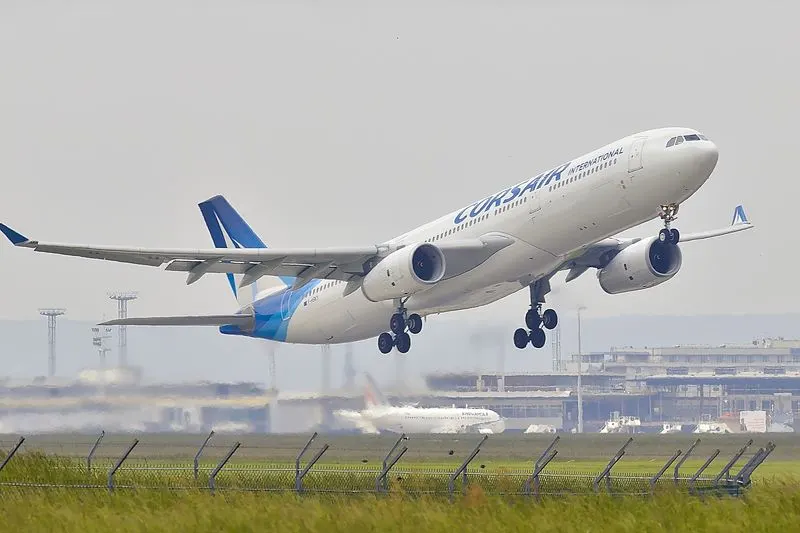
For light aircraft, usually full power is used during takeoff. Large transport category (airliner) aircraft may use a reduced power for takeoff, where less than full power is applied in order to prolong engine life, reduce maintenance costs and reduce noise emissions. In some emergency cases, the power used can then be increased to increase the aircraft's performance.
The takeoff speed required varies with aircraft weight and aircraft configuration (flap or slat position, as applicable), and is provided to the flight crew as indicated airspeed.
Operations with transport category aircraft employ the concept of the takeoff V-speeds: V1, VR and V2. These speeds are determined not only by the above factors affecting takeoff performance, but also by the length and slope of the runway and any peculiar conditions, such as obstacles off the end of the runway.
Tyre design :
When it comes to safety, tyres are one of the most important components of aircraft. They help to absorb the shock of landing and provide cushioning. It also provides the necessary traction for braking and stopping of an aircraft.
An aircraft tyre is designed to withstand extremely heavy loads while landing, take off, taxing, and parking. The number of wheels required for aircraft increases with the weight of the aircraft, as the weight of the aeroplane needs to be distributed more evenly.
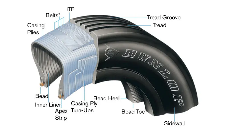
- They support the weight of an aircraft while it is on the ground.
- It also provides the necessary traction for braking and stopping of an aeroplane.
- Tyre also helps to absorb the shock of landing and provide cushioning the roughness of takeoff, roll-out, and taxi operations.
Unlike an automobile or truck tyre, it does not have to carry a load for a long period of continuous operation. However, an aircraft tyre absorbs the high impact loads of landing, and also it’s operating at high speeds for a short time when required.
Rolling resistance :
Rolling resistance, sometimes called rolling friction or rolling drag, is the force resisting the motion when a body rolls on a surface. It is mainly caused by non-elastic effects; that is, not all the energy needed for deformation of the wheel, roadbed, etc., is recovered when the pressure is removed. Two forms of this are hysteresis losses , and permanent deformation of the object or the surface . Another cause of rolling resistance lies in the slippage between the wheel and the surface, which dissipates energy. Note that only the last of these effects involves friction, therefore the name "rolling friction" is to an extent a misnomer.
Rolling resistance of an aircraft depens upon a lot of factors such as,
- Aircraft weight
- Tyre pressure
- Runway condition
- Weather conditions
Usually airplane have a very low rolling resistance coefficient such as 0.06.
Tyre Pressure :
Aircraft tyres are designed to withstand extremely heavy loadds for short durations.
The number of tyres increases along with the weight of the plan to ensure uniform distribution
Aircraft tires are not the same as passenger car or truck tires. As a result, their care and service requirements differ.

Some of the tyre pressure maintenance practices involves,
- Check inflation pressure daily or before first flight when tyres are cool. Tyre pressures should always be checked with the tyre at ambient temperatures as they can rise in excess of 93°C above ambient during operation. A temperature change of 3°C produces approximately 1% pressure change. It can take up to 3 hours or more after a flight for tyre temperatures to return to ambient. A tyre/wheel assembly can lose as much as five percent (5%) of the inflation pressure in a 24-hour period and still be considered normal. Tyre pressures change on a daily basis.
- When tyres are going to be subjected to ambient temperature differences between two locations in excess of 27°C, inflation pressures should be adjusted to the colder temperature prior to takeoff. This also applies when checking pressure in a heated hangar in the winter.
- Nitrogen should be used for tyre inflation as it will not sustain combustion and will reduce degradation of the liner material, casing plies and wheel due to oxidation. Appropriate regulatory agency requirements for nitrogen inflation should be followed.
- It must be determined if “loaded” or “unloaded” pressure has been specified by the aircraft manufacturer. When a tyre is under load, the gas chamber volume is reduced due to tyre deflection. Therefore, if unloaded pressure has been specified, that number should be increased by 4% to obtain the equivalent loaded inflation pressure. The opposite is true as well: if loaded pressure has been specified, that number should be reduced by 4% if the tyre is being inflated while unloaded.
- Excess inflation pressure should never be bled off from hot tyres. All adjustments to inflation pressure should be performed on tyres cooled to ambient temperature.
- To prevent one tyre on a gear from carrying extra load, all tyres on a single gear should be inflated equally. The mate tyre(s) will share the load, allowing individual tyres to run underinflated or overloaded if pressures are unequal, because all tyres on the gear will deflect identically.
- Inaccurate gauges are a major source of improper inflation pressures. Gauges should be checked periodically and recalibrated as necessary.
- Tyres that have been subjected to unusually high service braking or operating conditions such as high energy rejected takeoffs or high energy overspeed landings should be removed and scrapped. Even though visual inspection may show no apparent damage, tyres may have sustained internal structural damage.
Brake forces :
Aircraft brakes stop a moving aircraft by converting its kinetic energy to heat energy by means of friction between rotating and stationary discs located in brake assemblies in the wheels. Brakes provide this critical stopping function during landings to enable airplanes to stop within the length of the runway.
The following braking devices are used to decelerate the aircraft,
- Ground spoilers
- Wheel brakes including anti-skid systems and autobrake systems
- Thrust-reverser
6. Calculating the force and power required to push / pull an aircraft by a towing vehicle
The forces that are acting on the aircraft are
i) Rolling Resistence
ii) Drag Force
i) Rolling Resistence for an Aircraft
Rolling resistance is given by,
Fr =c. mr. g
Here from the above formula
Fr =Rolling resistence
c =coefficient of rolling resistence (0.005)
mr =rolling mass (50000 kg)
g =Acceleration due to gravity
Now Substituting the values in the above formula gives us the Rolling resistence of the Aircraft
Fr =0.005(50000)*9.81
Therefore the Rolling resisrence of the aircraft Frr=2452.5 N
Rolling Resistence for the Towing Vehicle is given by,
Fr = c. mr. ag
Fr = 0.002(78000 )*9.81
Therefore the Rolling resisrence of the Towing vehicle Fr = 1530.36 N
ii) Drag Force
Drag Force = `1/2 CdAV^2`
D = Drag force
C = Drag Coefficient ( 0.22)
V = Velocity of Towing Vehicle (5 m/s)
A = Frontal area (2)
Now Substituting the assumed values in the above formula gives us the Drag force of the Towing vehicle
Drag Force = (0.22*1.25*2*5*5)
= 6.87 N
Therefore the Drag force is = 6.87 N
The total force to push the aircraft by the towing vehicle is given by,
Ft = 2452.2 N + 1530.36 N + 6.87 N
Therefore the Total force required to a towing vehicle to push the aircraft = 3989.73 N
Torque required by the vehicle,
Torque = force x radius of the wheel
assuming the radius of the wheels = 0.4572 m
= 3989.73 * 0.4572
Torque = 1824.10 Nm
Therefore the Totque required to the towing vehicle to push the aircraft = 1824.10 Nm
Power required to the towing vehicle to pull the aircraft
Power = force * velocity
= 3989.73 * 5.0
= 19940
Power required for the towing vehicle 19.94 kW
7. Designing an electric powertrain to fulfill aircraft towing application
In this case an EV powertrain was to be designed with certain parameters.
Electric cars function by plugging into a charge point and taking electricity from the grid. They store the electricity in rechargeable batteries that power an electric motor, which turns the wheels. Electric cars accelerate faster than vehicles with traditional fuel engines so they feel lighter to drive.
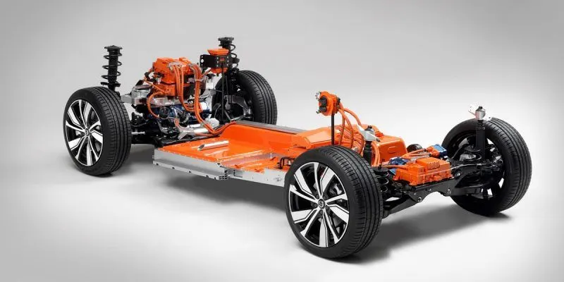
The various parameters involved in the powertrain include ,
- Power source
- Converter
- Electric motor
- Charger
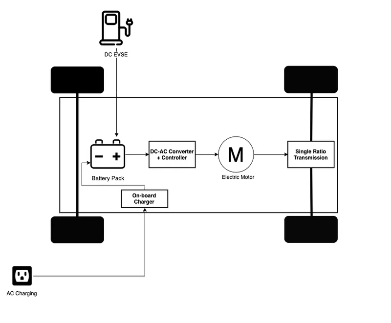
Battery Pack – The battery pack is made up of multiple Lithium-ion cells and stores the energy needed to run the vehicle. Battery packs provide direct current (DC) output.
DC-AC Converter – The DC supplied by battery pack is converted to AC and supplied to the electric motor. This power transfer is managed by a sophisticated motor control mechanism (also referred to as Powertrain Electronic Control Unit) that controls the frequency and magnitude of the voltage supplied to the electric motor in order to manage the speed and acceleration as per driver’s instructions communicated via acceleration/brakes.
Electric Motor – Converts electrical energy to mechanical energy, that is delivered to the wheels via single ratio transmission. Many EVs use motor generators that can perform regeneration as well.
On-board Charger – Converts AC received through charge port to DC and controls the amount of current flowing into the battery pack.
i) Motor Design :
Assuming
Type of Motor =BLDC Motor
Rated Power =20-25 kW
Peak Power =50 kW
Speed =3200 - 5000 rpm
Rated Torque =380 Nm
Peak Torque =160 Nm
Efficiency => 80 %
ii) Power Rating :
The rated power of the Motor is 25kW and the peak power of the motor is double the rated power of the motor which is 50kW
The Converter used in this is DC - AC Converter
Input Voltage =349 V
Input Current =70 A
Power Input =Voltage x current
= 349 * 70
= 24.30 kW
Power rating of the Electric motor is 24.30 kW
iii) Energy Requirements :
The Energy requirement for an EV similar to the Towing vehicle to Push/Pull the aircraft is calculated,
Let Energy = Power x Time taken by the towing vehicle to push/pull the aircraft
We know that Power is 24.30 kW
Time Taken by the Towing vehicle to push/ pull the aircraft =15 Minutes
So, Energy =24.30 x 15 x 60
= 21870 KJ
= 6.075 kW
Power required for one single towing is 6.075 kW
iv) Duty Cycle :
Here in this case the Duty cycle of the electric power train is calculated by the output power by the input power.
by this we get the efficiency of the duty cycle
So here in this case,
Duty Cycle = Output Power / Input Power
We Know that,
Output Power = 19.94 kW
Input Power =24.30 kW
Then the Duty Cycle is =19.94 / 24.30
= 0.82
Efficiency of the Duty cycle that we get for this electric power train 82 %
CONCLUSION :
All the given objectives were satisfied with atmost perfection.
The calculations , images and files were attached wherever necessary.