Base Unit Design 2
AIM :
To study about the various design aspects regarding BIW fixtures.
OBJECTIVE :
- To design a Base Unit for the units designed for the above challenges with all weldments for the given Car Panel.
- To combine all the fixtures together to create the final assembly.
Base Unit
Base Unit is one of the most significant unit of the fixture design because the entire fixture assebmly is mounted over it.
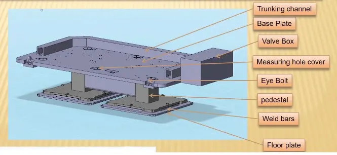
The various parts of a Base Unit are,
- Base Plate
- Pedestal
- Trucking channel
- Valve box
- Eye bolt
- Floor plate
- Weld bar
Base Plate
- Base plate is a machined plate of 25 to 40 mm thickness.
- It is generally made up of steel and aluminium.
- The various units such as clamp unit, pin unit etc., are mounted on the base plate using drilled holes.
- A base plate should cover all the units with its outer periphery including opening.
- Datum holes must be covered using cover plates.
Pedestal
-
A pedestal is a part which connects the base plate to the floor plate.
-
In general a pedestal is a standard part and in some cases it can be a welded frame integrated with the base plate.
-
A standard pedestal can be of different height and different sizes.
-
Depends on the size of the base plate, the number of pedestal varies for load distribution.
-
A pedestal are of different types with different inclinations.
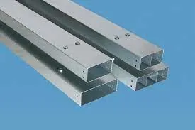
Trunking channel
-
A trunking channel is a duct which accommodates all the pneumatic and electrical hoses and wires for the units of the tool.
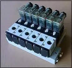
Valve box
- Valve box is a standard part which will accommodates the pneumatic valves for the units.
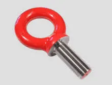
Eye bolt
-
Eye bolts are used for the transporting of the tool from one plate to another.
-
This can be done using lift hooks, fork lift holes will also be provided in some cases for transporting purpose.
Floor plate
- Floor plate is grouned to the floor with fixed bolt on the ground.
- These plates are also called as foundation plates.
-
There will be a clearance of 10mm maintained between the pedestal base plate and the floor plate.
-
This clearance will be used by the levelling screws, for levelling the entire tool.
Weld bar
- Weld bars are be used to weld the positions permanently , after levelling is done.
- A weld bar is a plate along the sides of the base plate of the pedestal.
Design Aspects of a Base Unit
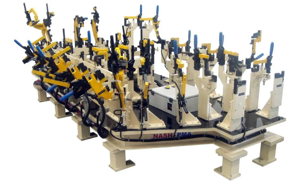
The various points that has to be considered while designing a Base Unit are,
Working height
- Working height is an important aspect while designing a base unit.
- It generally depends on the nature of welding.
- A working height of 850 to 1100 mm is considered for a manual fixture which actually depends on the country.
- If the base plate has a tubular structure, the working height may increase by 100 to 250 mm.
- Andditional leg structure may be provided to reach an adequate working height.
Size of the Base plate
- Size of the base plate must be known for the design purposes.
- It is useful during fabrication process and it improves the overall handling.
- Proper flattening of the base plate must be ensured when the base plate is very long.
Eye bolts for the assembly are selected by considering the weight of the enitre assembly.
Its location also needs to be taken care of depending on the type of hooks or belts used in order to ensure that there is no damage to the adjacent parts in the asembly.
Depending on the size and weight of the assembly, fabricated plate can be used or a normal plate can be used when there is no such requirements.
Fixed Pin Unit
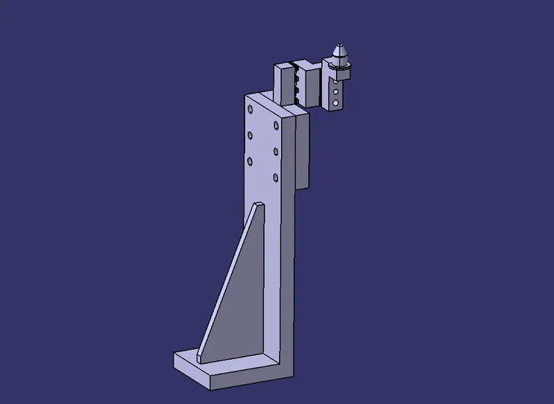
The Fixed pin unit is designed to locate the car pannel using different types of pins.
The various parts of a fixed pin unit are as follows,
- Pin
- Pin Reatainer
- Shims
- Block
- Blade / Adaptor plate
- Riser
Retractable Pin Unit
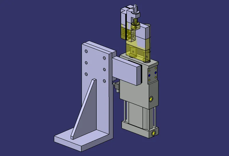
The Retractable pin unit is designed to locate the car pannel using different types of pins.
It differs from fixed pin unit with the use of pneumatic cylinders.
The Pin unit will be mounted on the Cylinder.
It contains the same components as that of the Fixed pin unit except the cylinder.
Pneumatic cylinder
Pneumatic cylinders help in the opening and closing of the pin unit, which helps in the mounting process.
The two types of pneumatic cylinders used here were,
- Single rod retractable cylinder
- Double rod retractable cylinder
Clamp Unit
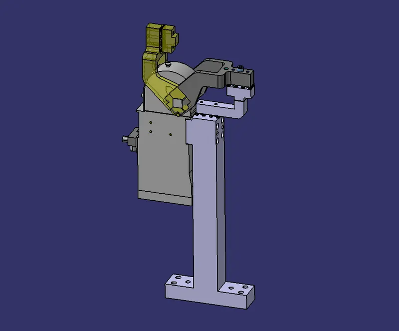
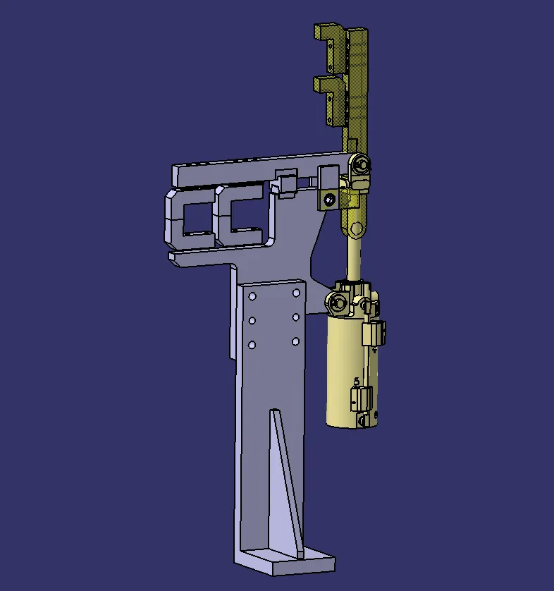
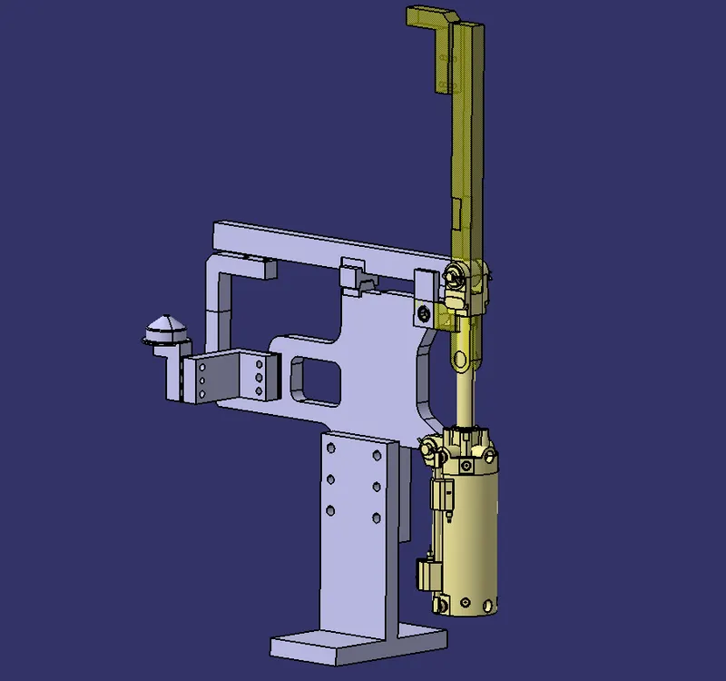
A Clamp unit is a unit which is designed to clam or hold the car panel.
The various parts of a Clamp unit are as follows,
- Clamp Arm
- Clamp Cylinder
- Finger
- Rest
- Shims
- Plate
- L Block
- Riser
Rest Unit
A Rest Unit is used to support the entire car pannel from underneath.
It is a simple unit which used only used to support the panel.
In order to save the overrall cost, it can be combined with other unit such as locating unit.
The various parts of a fixed pin unit are as follows,
- NC blocks
- Shims
- Blade
- Riser
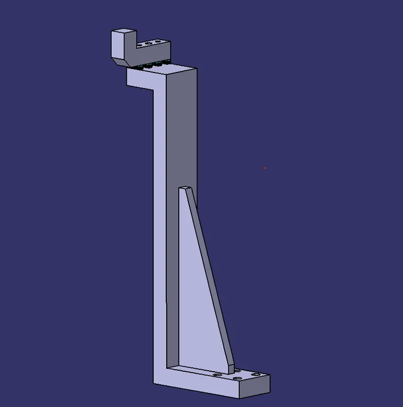
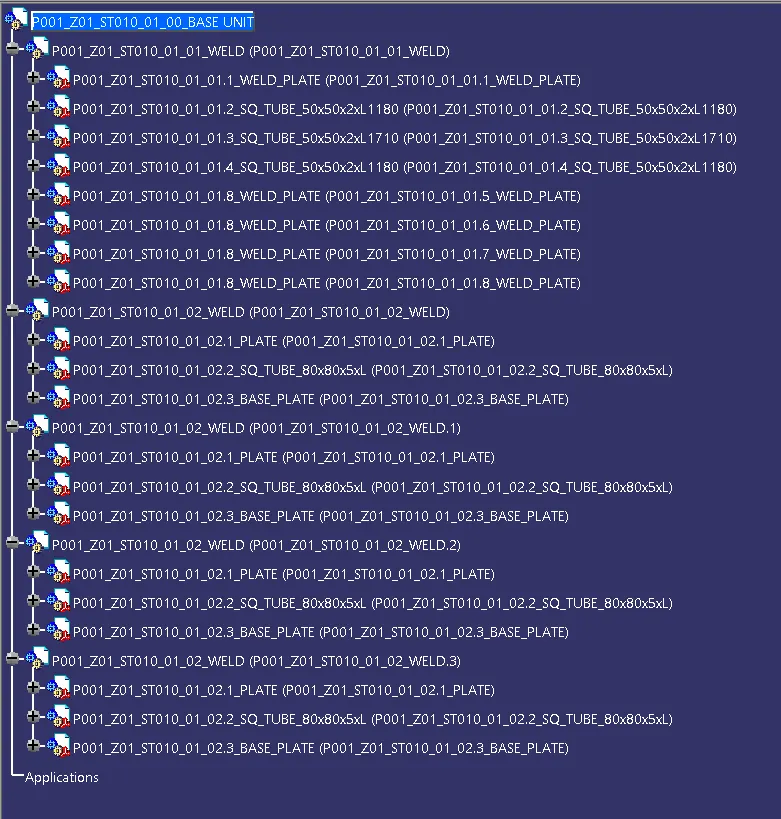
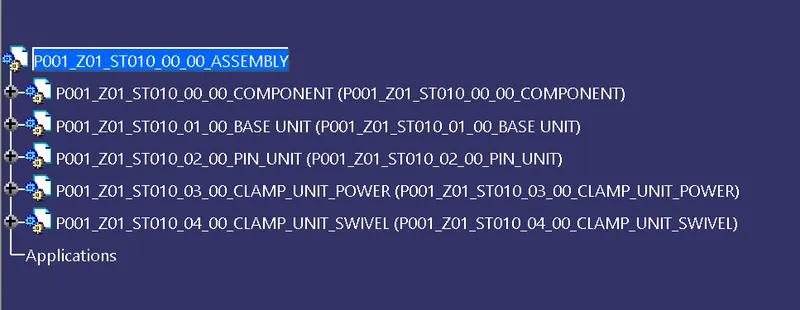
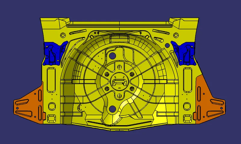

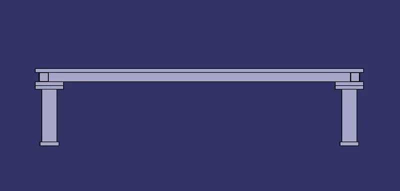
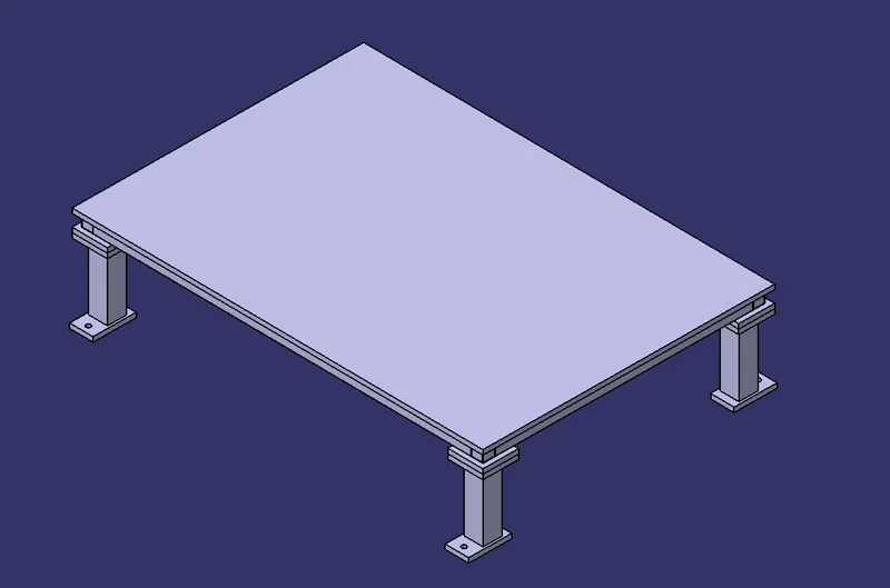
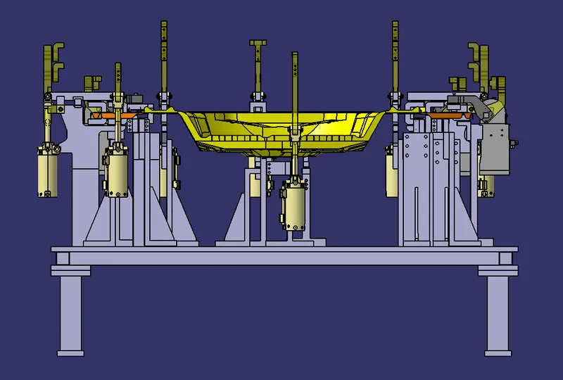
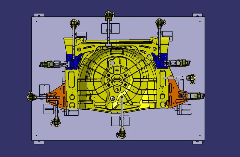
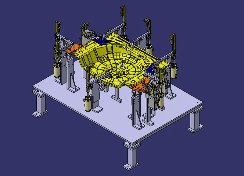
- The Base unit was created with proper design methodologies.
- The Complete Fixture Assembly was created with proper design methodologies.
- Necessary images and part files were attached.