Week - 5 - Modelling Spotwelds
AIM:
Create Spotwelds between the given two parts with the beam element as case 1 and use Hexa element in case2, now comparet the results of both the case and conclude the same
Steps Followed:
Create section and material for parts:-
- Import the model to the LS pre post
- Check for the available keywords from keyword manager
- Initially we have to create the required keywords/cards
- Create a section card, go to keyword manager>Section>Shell
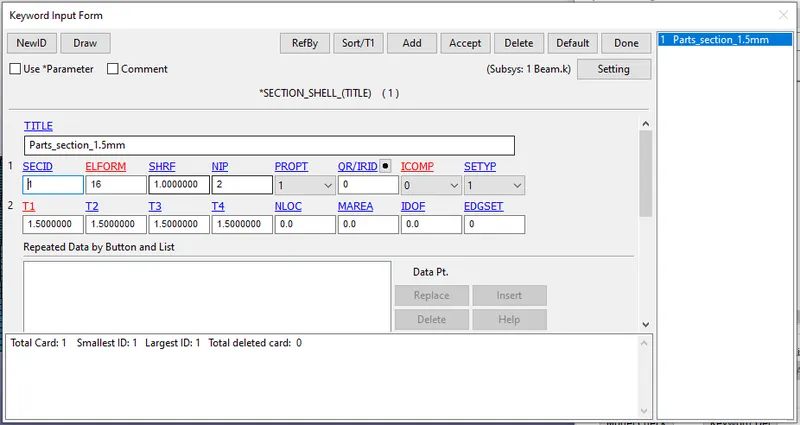
- From the above image we can see the section card for part, give the thickness as 1.5mm for the shell
- Create a material card for the same, go to keyword manager>MAT>piecewise linear plasticity material
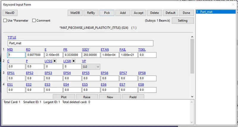
- Now assign the section and material card to the respective parts
Create Rigidwall:-
- Now create a rigidwall, go to create entity>Rigidwall>create>Planar
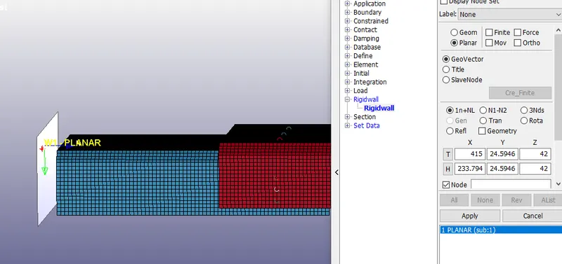
- Make sure the normal of the rigidwall is faced towards the parts
Create initial velocity card:-
- Create a initial velocity card, go to keyword manager>Initial>velocity node
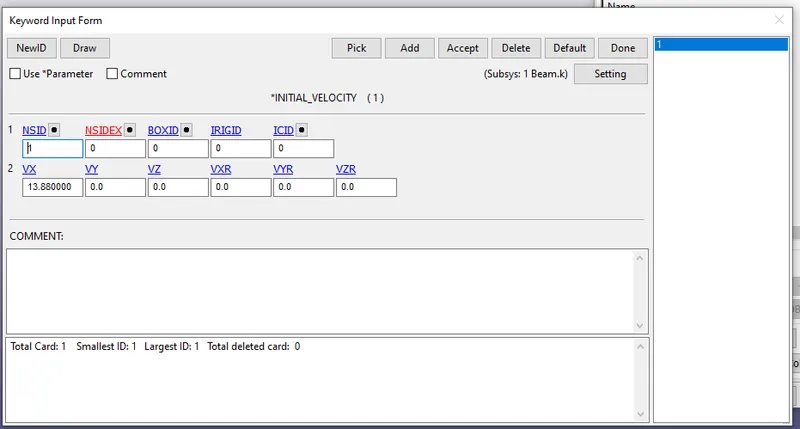
- From the above image we can see the velocity used same as in week 4 challenge
Create Beam(Case 1):-
- Now we have to ceate a spotweld using beam
- Go to Element and mesh>Element generation> Beam slect beam by option to two node set
- Select the two nodes to be connected by beam
- Below image shows the beam created
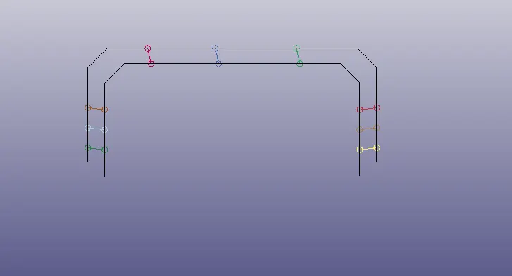
- I have created total of 9 beams symmetricaly
Create section and material for Beam:-
- When the beams are created the respective sections will be created, delete all the section and create new one
- Go to keyword manager>section>beam
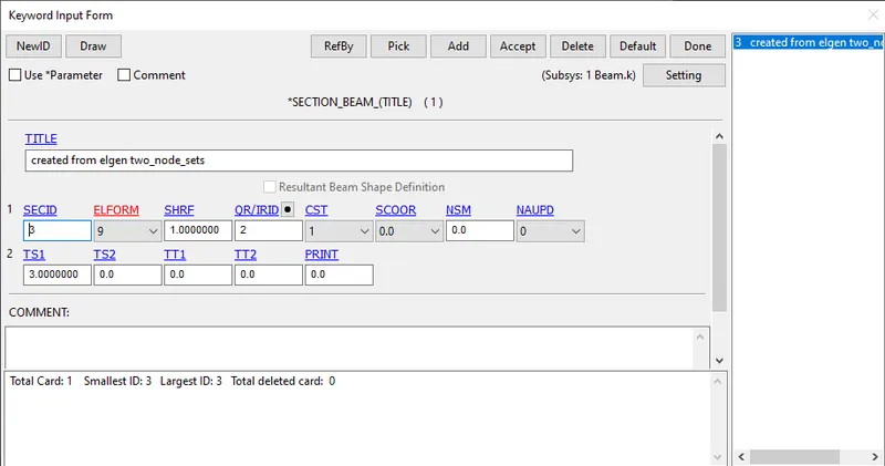
- Use ELFORM=9 for spotweld representation, used thickness as 3mm as shown in the above image
- Create material card for spotweld, go to>keyword manager>mat>MAT 100
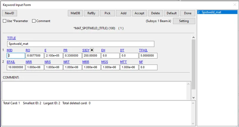
- From the above image we can see the material card for spotweld, mat100 material is used s=for spotweld, The failure criteria is given to the material and time based failure is also specified as 5ms
- Now assign the material and section card for the beam
Create Hexa element(case 2):-
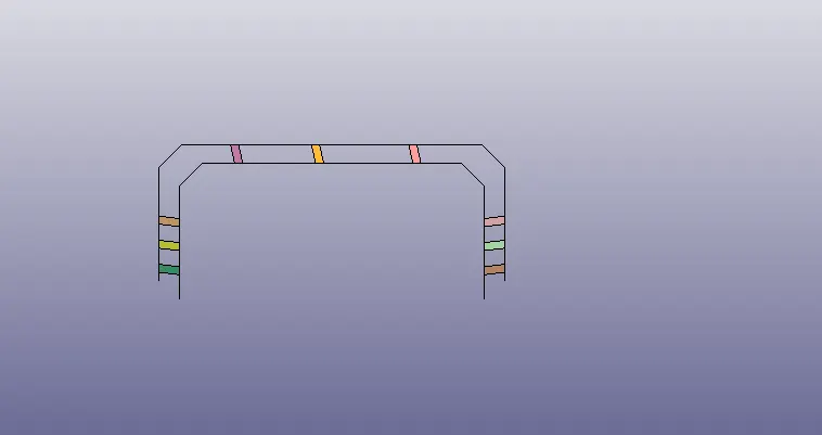
- Create spot welds as hexa elements
- go to>Element tools>element editing>create>elem type>HEXA
- Create the hexa in the same points where the beams are created
Create Section and material card for HEXA(Case 2):-
- Use the same material used in case 1
- Section card is created newly for hexa elements
- go to keyword manager>section>solid
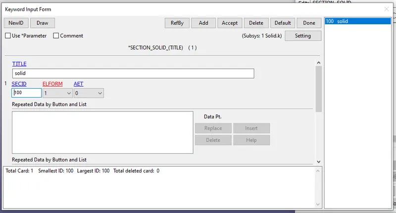
- Assign the section and material card to hexa part
Create contact cards:-
- Create an automatic_single_surface to avoid the initia l penetration between the parts(go to keyword manager>contacr>Automatic_Single_surface)
- Select the both the parts and create as single part set, in this contact select only the master node
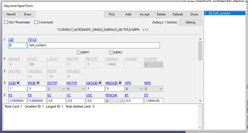
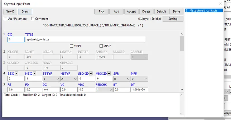
- Create the contact between the welds and parts by keeping the parts as master and welds as slave
- Go to keyword manager>contact>TIED_SHELL_EDGE_TO_SURFACE
Create control and output cards:-
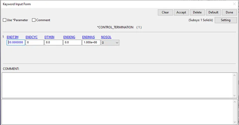
- Create termination card go to keyword manager>control>termination, end time=10ms
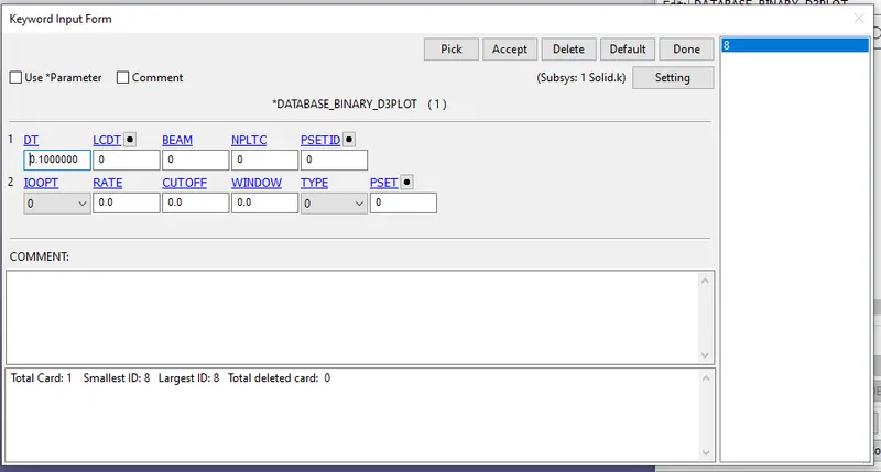
- Create Database cards like ASCII, BINARYD3PLOT
- In ascii option use ELOUT ,GLSTAT, MATSUM,NODOUT, RWFORC , SLEOUT, SWFORC cards with DT=0.01ms
- Binary card is shown in below image
RESULTS:
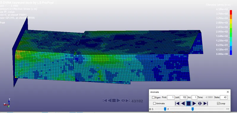
Case 1:
- Von-mises=4.12E+02Mpa
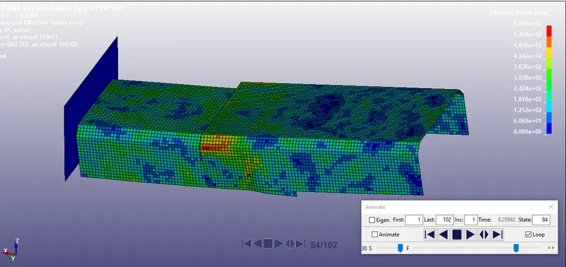
Case 2:
- Von-mises=6.06E+02Mpa
- Kinetic energy of beam and hexa element are noted down in the same loacation, the results are shown in the below image
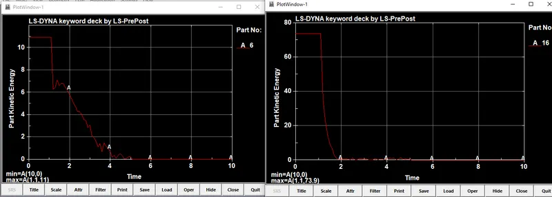
- In the above image the left side graph shows the plot for beam element and right one is for Hexa element
- Part Kinetic energy for case 1= 11
- Part Kinetic energy for case 1= 73.9
CONCLUSION:
- From the above results we can see the von misess stress is more for solid(Hexa) element compared to Beam element
- It is known now the hexa element hold good for spotweld instead of beam element
- The part kinetic energy is also high in hexa element