Week 8 - Universal Joint
OBJECTIVE:
- To set the Universal joint with a spring in Transient Analysis system
Steps:
Import Geometry:-
- Import the geometry from the saved location
- Import the required materials from engineer data madule
- Open the imported model in space claim and look for any abnormality in Geometry
Mechanical Workbench:-
- Rename the Geometry if needed for convinience
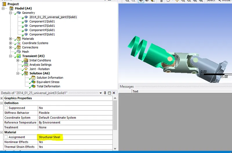
- For case 1 use Structural steel for the Joint with springs as shown below
- For case 2 use Stainless steel for the same part
- For case 3 use Titanium Alloy for the same part
- Delete all the default contacts, because we are not worried about contact
Define Joints:-
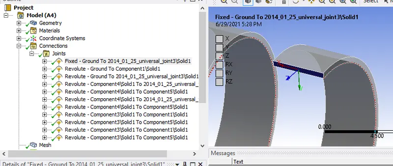
- Define Fixed Body to ground joint for Spring edge face
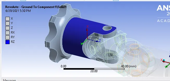
- Define Revolute body to ground joint for part which is driven by some gear
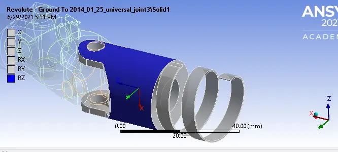
- Revolute Body to ground joint for part with springs, make sure the direction of rotation is proper
- Now we have to define Body to Body Revolute joint for all the eight Pin joints, in this Mobile and reference surfaces is shown below
Mobile surfcae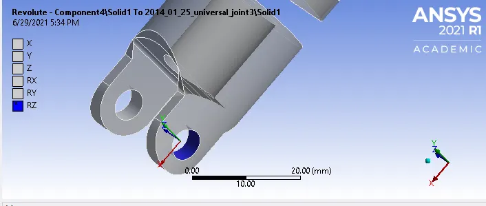
Reference surface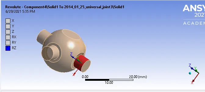
- Do the same for all the eight pin joints, make sure the direction of rotation is proper
Create Mesh:-
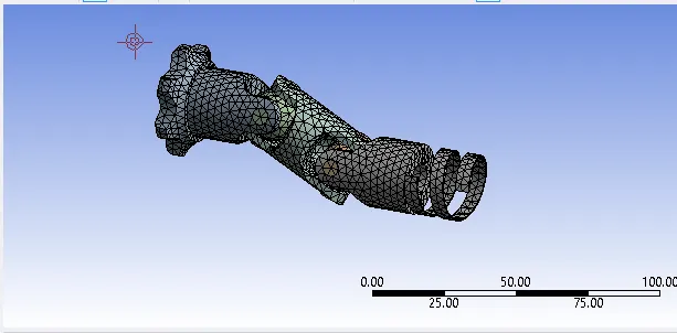
- Create a finer mesh where the node limit is within academic version's limit
- In this case i have used 3mm mesh element size
Analysis setting:-
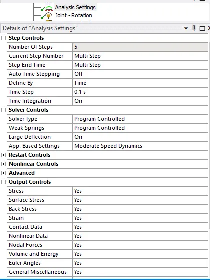
- Create a analysis setting with 5 steps
Define Joint Load:-
- Define the created revolute joint on the part which is driven by some gear
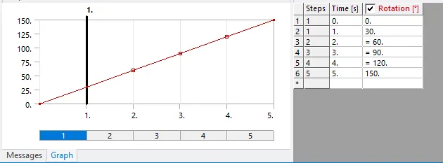
Results and Conclusion:-
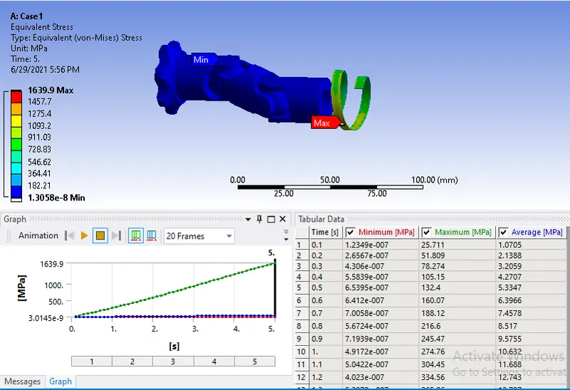
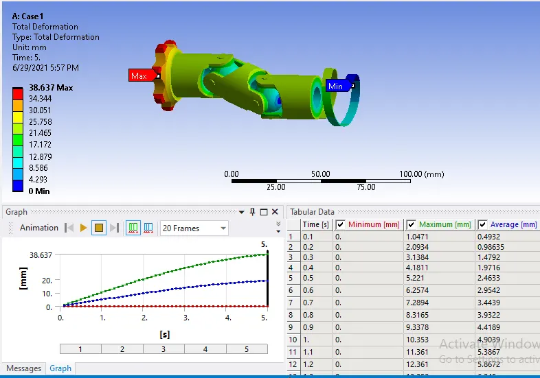
Case 1 :-
- Equivalent Stress
- Total Deformation
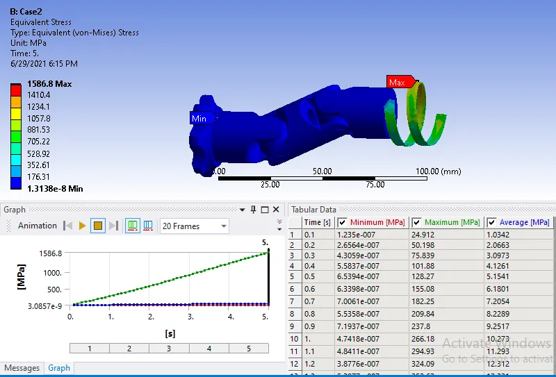
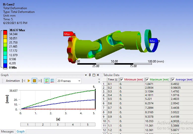
Case 2 :-
- Equivalent Stress
- Total Deformation
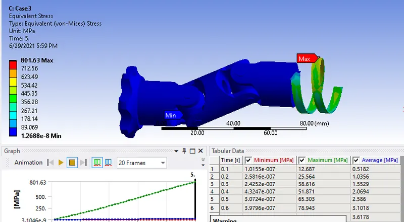
Case 3 :-
- Equivalent Stress
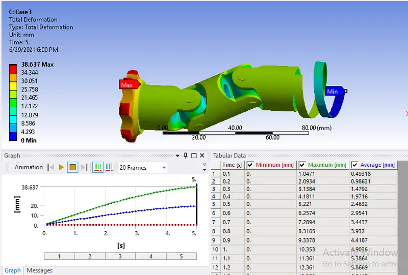
- Total Deformation
-
Case Equivalent Stress(Mpa) Total Deformation(mm) 1 1639.9 38.637 2 1586.8 38.637 3 801.63 38.637 - From the above results we can see there is no change in the Total Deformation, even though there is different material
- The stress generated in the case 1 is higher than other two
- This is due to the density of the material, higher the density of material higher the stress generated