Project 2
AIM: To model the given component by Mid surface and Tetra mesh depending on the need and provide appropriate connection to the same
PROCEDURE:
Step 1:-
- Once the model is imported into the software , firstly perform TOPO and check for the Geometry error
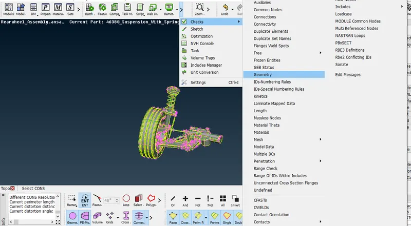
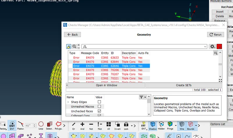
- The above image shows the number of geometry error present in the model, try to fix manually or using Auto option
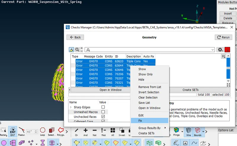
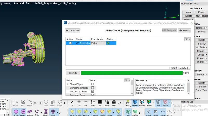
- above image represents once all the geometry errors are fixed
Step 2:-
- Once all the errors are fixed next step is to segregate parts which are having thickness less than 5mm
- Mid surface will be extracted and meshed to parts having thickness less than 5mm
- Parts with more than 5mm thickness will be considered as solid and tetra mesh is performed.
- For the given model there are different quality criteria for different sets of parts
- Tyre and rim has one quality criteria, Other solid parts has a seperate quality criteria and parts less than 5mm thickness has different quality criteria
- Save all the differnt quality criteria and mesh parameters seperately
Step 3:-
- Starting with, firstly find the parts with thickness less than 5mm
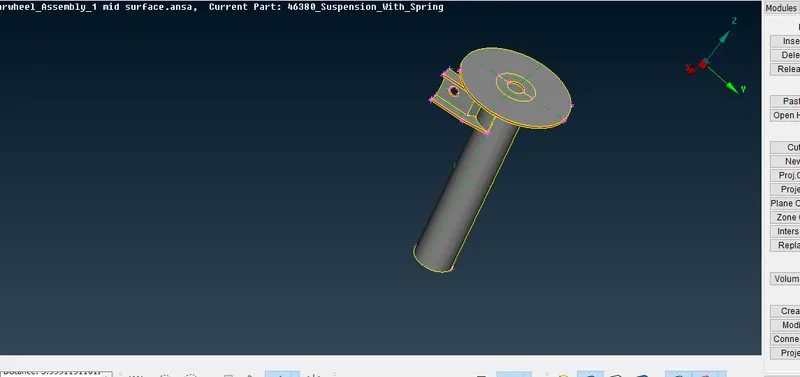
- Mid surface should be extracted to the model shown in the above image
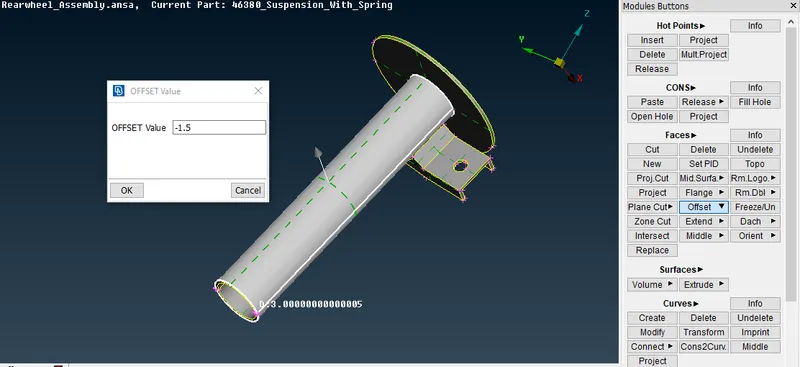
- Above image shows the mid surface extraction by offset option by giving the value as half the thickness
- Set Property ID for the mid surface extracted and assign the respective thickness
- Mesh the mid surface according to the given quality criteria and make sure there is no OFF elements
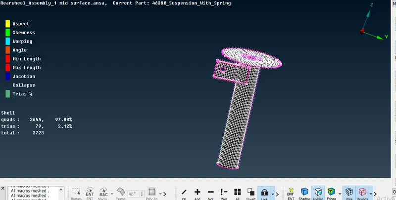
- Above image shows there is zero OFF elements and the mesh satisfying the criteria
Step 4:-
- Next step is to perform mesh on the solid in mesh deck and assign the volumes for each part in volume mesh deck
- Isolate each parts and start meshing the circular region using ortho tria elements and flat region using tria elements
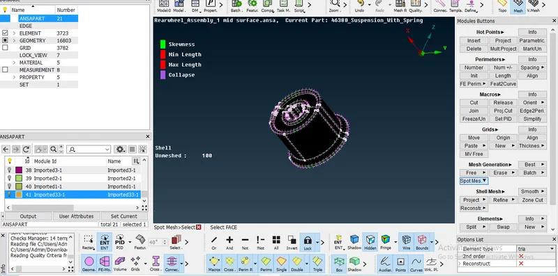
- De-feature the Features which does not satisfies quality criteria
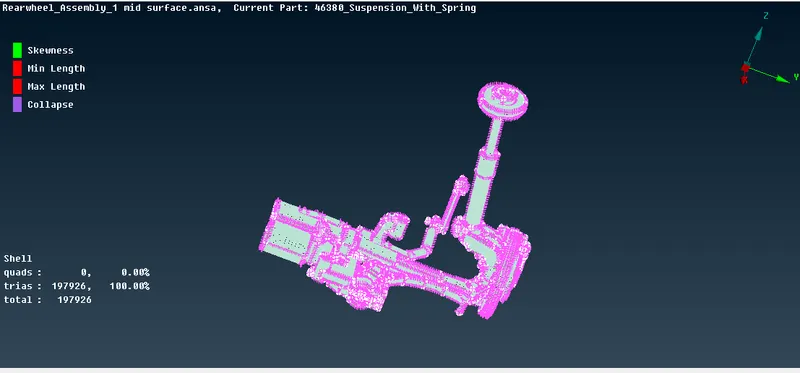
- Make sure there is no maximum and minimum length error are present in the solid mesh
- Repeat same step for all the other parts except tyre, rim and Spring.
- Below image shows the solid mesh of all the other parts, No OFF elements present
Step 5:-
- Step 4 should be carried out for tyre and rim portion, only difference is change in quality criteria
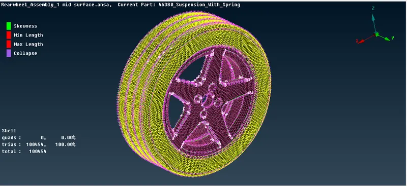
- The above image shows the fully meshed tyre and rim part with zero OFF elements
Step 6:-
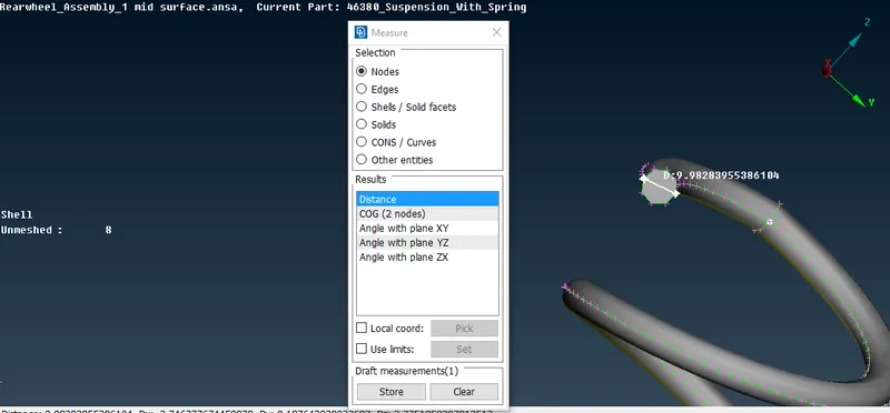
- Next is to model spring component as 1D bar element(in Reference to WEEK 6 Session 3 article)
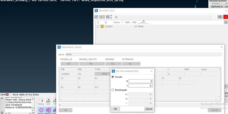
- Create middle curve for the spring, select the curve and assign CBAR element
- Measure the dia of the spring , so it will be helpful in assigning the area for the 1D element
Step 7:-
- The volumes has to be assigned to the solids in volume mesh deck
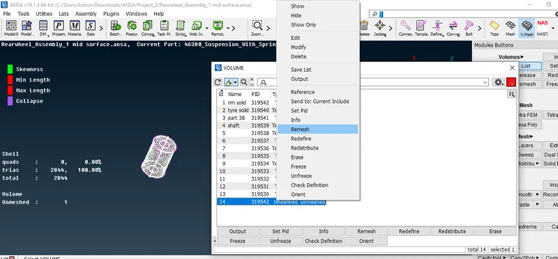
- isolate the meshed body and define the volume by Volumes>Define>Auto
- Defined volume will be in list without mesh, right click and remesh(as shown in below image)
- Now the mesh can be performed in either Tetra rapid or tetra FEM algorithm(As shown below)
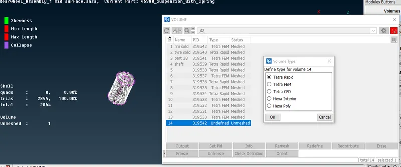
- Set PID for the defined volume
- Repeat the above steps for all the solids
- Below image shows the representation once the volume is assinged
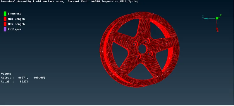
- Try fixing the tet collapse issue by fix quality option if the error occurs somewhere inside the volume
- If error occurs on the surface , then use MV free option and try to adjust the kinks and rise edges
- Make sure there is no Kinks and Rises in volume
Step 8:-
- Next step is to move to nastran deck and establish all the connections which is present
- Provide Rigid body connection wherever required using RBE2 many nodes option
- RBE2 two nodes option will be used to represent the body of the bolt
- Next is to establish connections of seam weld
- Convert the cons to Curve and convert the curve into seam line(as shown below)
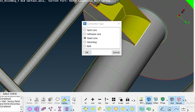
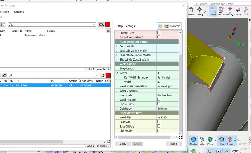
- Using connection mangaer define the weld PID, type of weld like Y-joint shell or Overlap shell
- If the two bodies to be welded are parallel to each other use over lap shell
- if the bodies are perpendicular to each other use joint shell
- Weld definitions are shown in below image
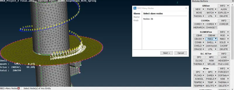
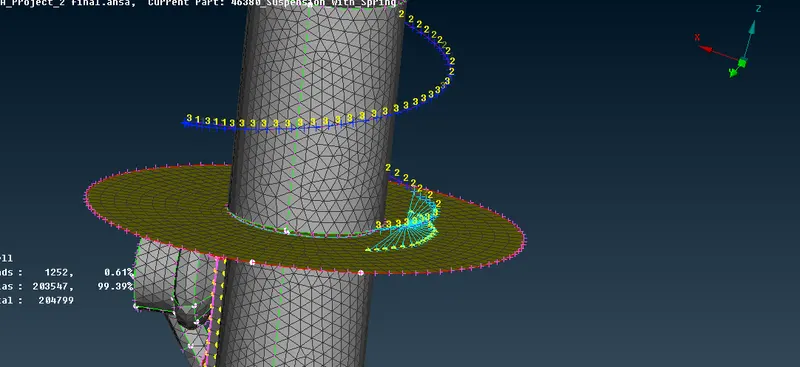
- Next connection is between the spring and corresponding component
- Use RBE2 many nodes connection and establish the connection
Step 9:-
- Once all the rigid body connection and seam weld connection are done
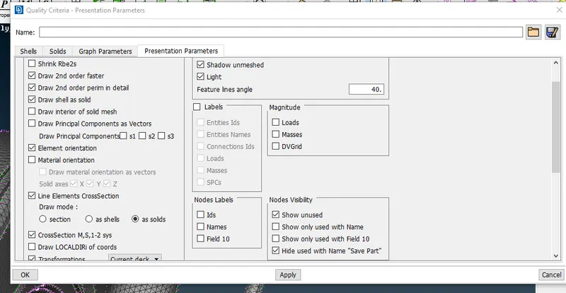
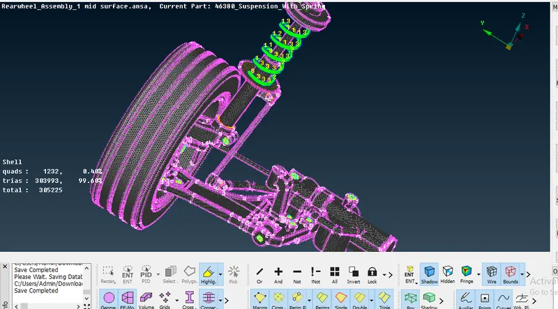
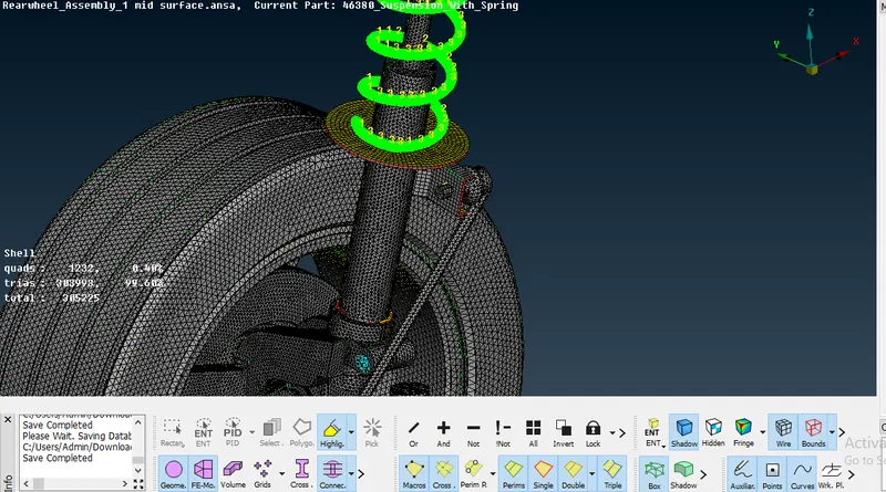
- Enable draw Shell as solid for the mid surface created and enable Line elements cross section>draw mode > solids for 1D bar element as show in below image
- Final results shown below
LEARNING OUTCOMES:
- Learn the connections for counter bore holes and counter sink holes
- Understood how to connect Mid surface and solid using RBE2 two node method
- Understood connection of 1D bar element
CONCLUSION:
- The given model is fully meshed and appropriate connection is done
- The complication in the model gave the confidence over the tool
- Both the project helped me to understand the different options in ANSA
FINAL MODEL:
https://drive.google.com/file/d/1dpgor1KuMAhAjfkZycbjzuQfgU_ARmLG/view?usp=sharing
Facing problem in uploading the file , the above link is the complete project 2 file please go through the same