Week 2 Railwheel and Track
OBJECTIVE:
- Set up the model for structural analysis and compae the results with different case
- Create a uder defines solution and compare it between both the cases
STEPS Carried Out:
Create contact:-
- Import the geometry and open it in mechanical module to set up the model
- First rename the contact based on definition for easy understanding
- Flip the contact and target, establish connection between shaft and wheel, Wheel and track
- Connection between shaft and wheel should be fricionless contact
- Connection between Wheel and track should be frictional type with 0.3 co-fficient
Create Joint:-
- Create fixed joint for the track, this joint is for making the track fixed
Connection type=Body to ground
Type=Fixed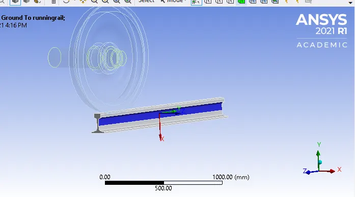
- Create translation joint on shaft, make sure the translation is in proper direction
Connection type=body to ground
Type=Translation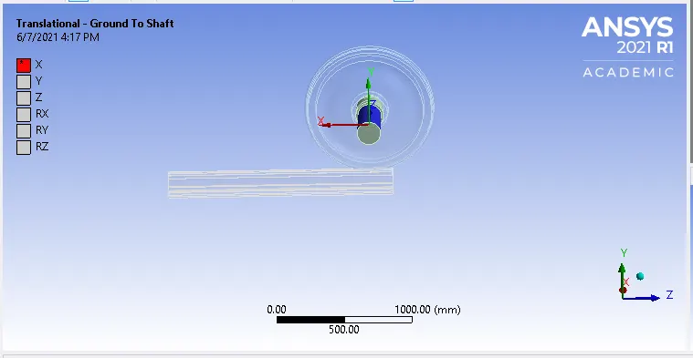
- Create planar joint
Connection type=body to ground
Type=Planar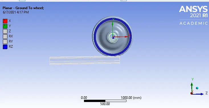
Mesh
- Mesh the components with 50mm element size
- Use face sizing in the contacting faces with 35mm element size
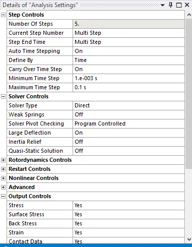
Analysis settings
- Analysis setting for 1 st step is shown in below image
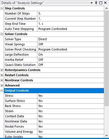
- Analysis setting for 2nd to 5th step
Create joint load:-
- Define joint load for the translation joint created before
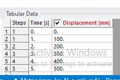
- Apply bearing load of 100KN in negative y direction on the wheel
- Reapeat the same step for next case , only change will be bearing will be 500KN
- Sizing and global mesh size should be 35mm
Output Request:
Case1(100KN):-
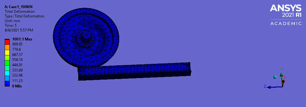
- Total deformation
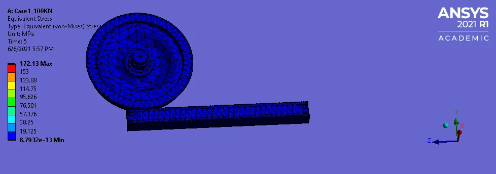
- Von mises stress
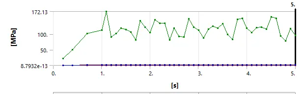
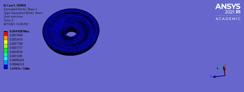
- Von mises Strain
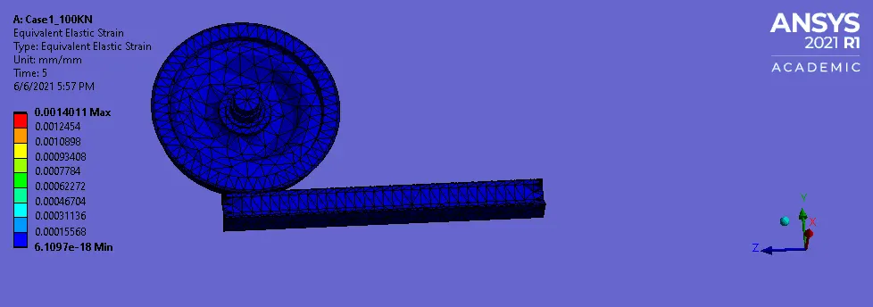
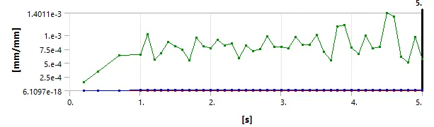
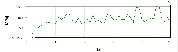
- Von mises stress for wheel
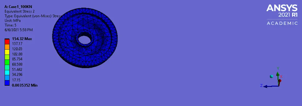
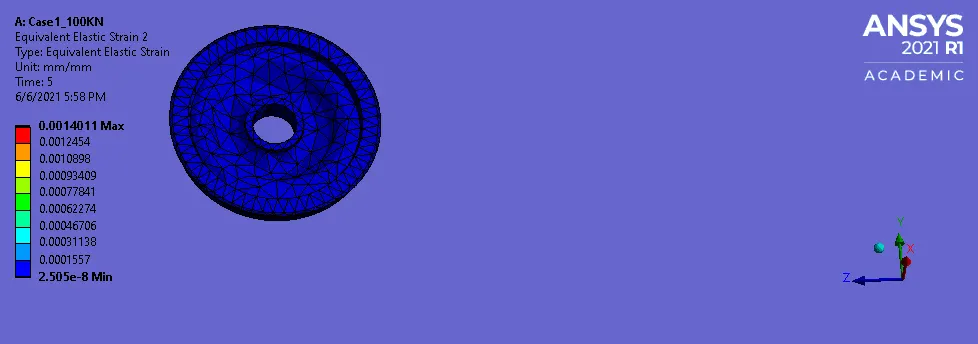
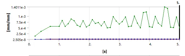
- Von mises strain for wheel
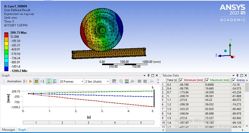
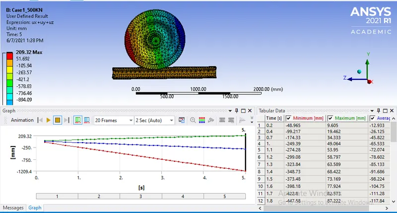
- User defined solution
Case2(500KN):-
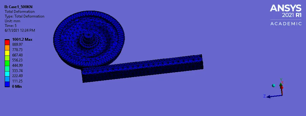
- Total deformation
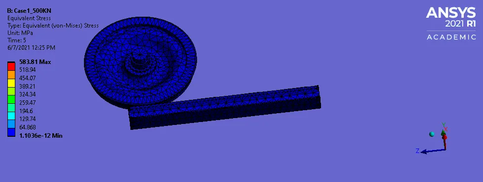
- Von mises stress
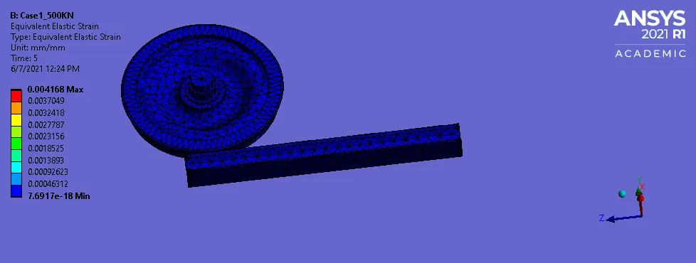
- Von mises Strain
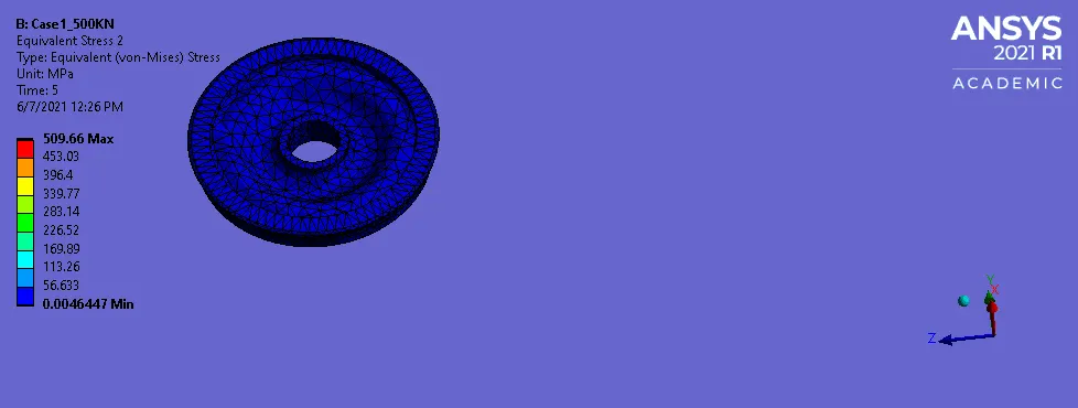
- Von mises stress for wheel
- Von mises strain for wheel
- User defined solution
RESULTS:
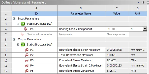
- Case 1(100 KN) results
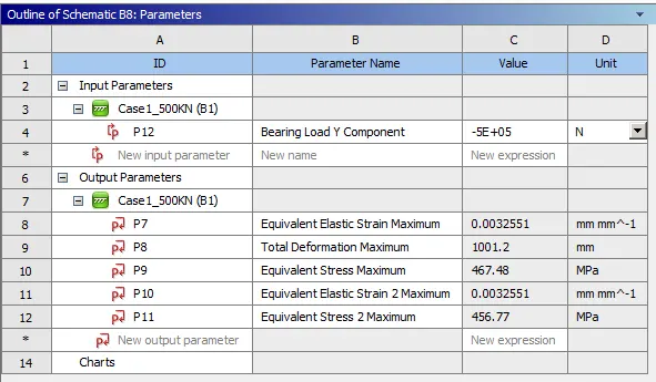
- Case 2(500KN) results
- Create user defined solution for both the cases, for displacement and compare it with total deformation
- the expression for user defined solution is ux+uy+uz
- Case1 100KN
User defined=209.75mm; Total deformation=10001.1mm - Case2 500KN
User defined=209.32mm; Total deformation=10001.2mm
CONCLUSION:
- From the above results we can see the deformation is same in both the case
- Von mises stress is more in the case 2 , due to finer mesh
- Von mises stress on wheel is also more in case 2
- We can see the default deformation is more than the user defined