Week 12:Project 2-Meshing of Rear Wheel Holder challenge
AIM: TO Extract the mid surface and mesh the given model according to the mentioned quality criteria
PROCEDURE:
Step 1:-
- Import the cad model into the software
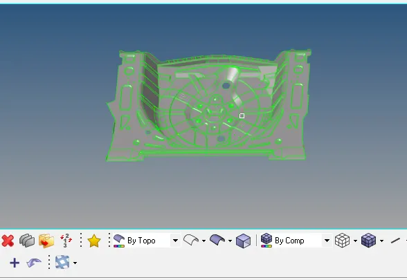
- Look for the missing surfaces, Damaged surfaces and Free edges correct them
- A missing surface is shown in below image
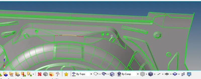
- We can toggle the edges and correct the free edges
- Damaged surface can be deleted and new surface can be created using filler surface or Ruled surface creation option
Step 2:-
- After correcting the geometry errors we have to extract the mid surface for the model
- Autocleanup the model by tools>autoclean up, using above quality criteria given
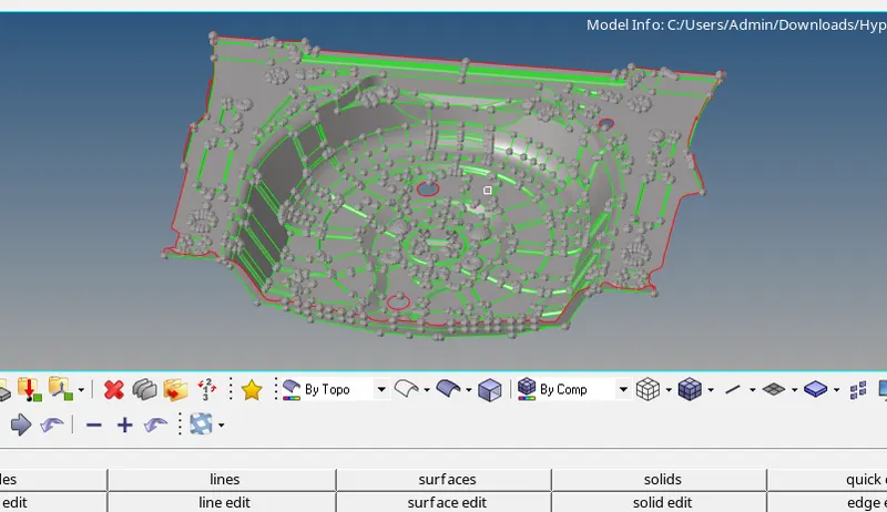
- Extract the mid surface using 2d>automesh option
- Extracted mid surface for the model is shown in below image
Step 3:-
- Check the mid surface for damaged faces and free edges
- Defeature few features which might fail for quality criteria
- Before meshing the model , split the surfaces into small portions to control the mesh flow
- To split the surface go Geom> quick edit> split surface using node to noide or node to line
- Make sure the mesh flow should not be disturbed when the surfaces are splitted
- So go to options(shortcut key O)>mesh> Keep mesh
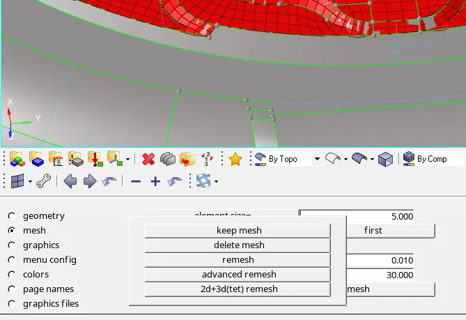
- Use "keep mesh" option when the surfaces should be split
- Use "Advanced remesh" option when the surfaces are meshed
Step 4:-
- Mesh the surfaces portion by portion , so that the quality errors can be be fixed simultaneously
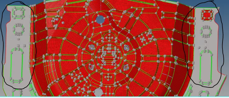
- Few feature are symmetric in the model, so instead of meshing the features again , we can mesh on one side and reflect the same to the other side
- Symmetric features are shown in below image
Step 5:-
- To peform reflect operation first we need to have a base point
- inorder to create base point, go to distances and mesure the distance between two symmetric points and use create nodes between option
- This will create point exactly between two points
- Now go to Tools>reflect select the elements which has to be copied to the other side
- Before reflecting the elements make sure duplicate of the elements have been created to the current component
Step 6:-
- Correct all the mesh flow and failed quality criteria
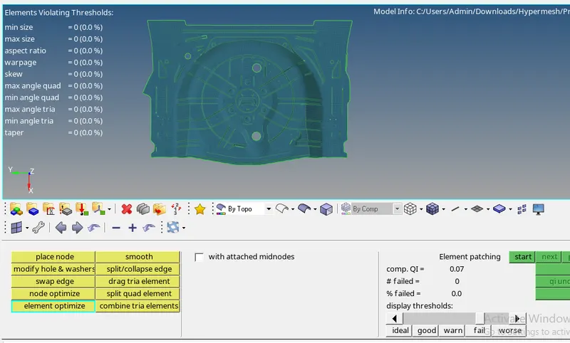
- The above image shows there are no quality erros in the model
- Now we have to check for free edges or for equivalence
- Inorder to check this go to Tools>Edges>select elements and finf the eqivalce and free edges like shown in below image
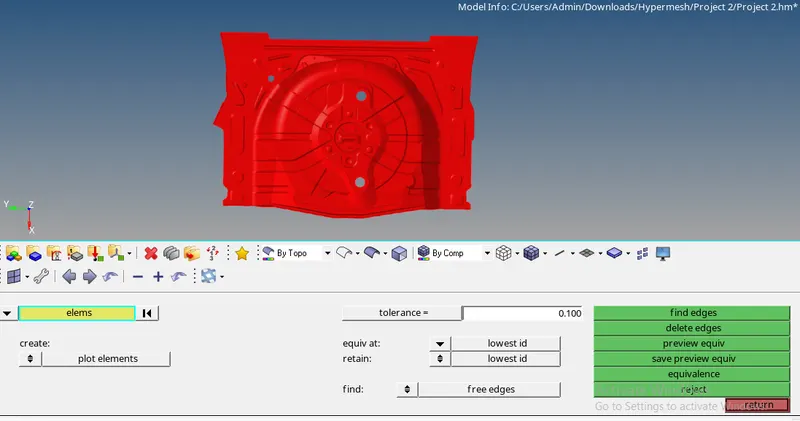
- By this option we will have knowledge of gap in the model and connections of elements to one ohter
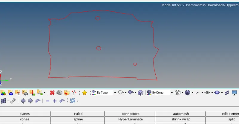
- If you see any unwanted free edges that is apart from the boundary of the model, fix it using 2d>replace option
- Below image shows theres no unwanted free edges
Step 7:-
- Next to assign the thickness and material for the mid surface
- Right click on the blank space under the model section, create property and material
- Since there is no mentioning of which material should be used i will be using default Mat1 card, it is of steel properties
- Next create Property for the mid surface as shown in below image
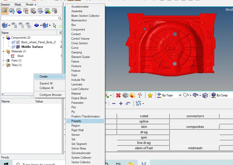
- For property default Pshell property card will be used here
- We should mention the thickness in property card so that the same wil be assigned to the component
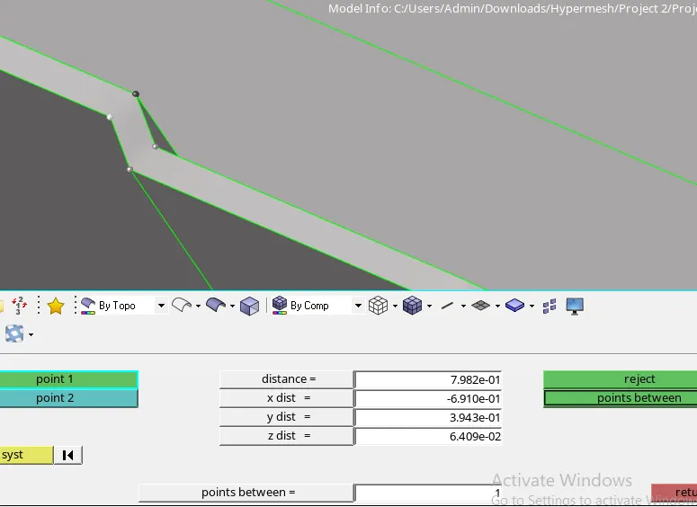
- On an average the measured thickness will be 0.78mm, so the same will be given in property card
- Right click on the mid surface component and select assign
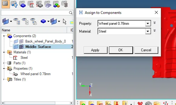
- Final result is shown in below image
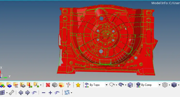
CONCLUSION:
- Understood how to correct the damged faces
- Understood how to stitch the elements together
- Understood the concept of extracting mid surface
- Understood how to controll the mesh flow
- The given model mid surface is extracted and meshed according to the criteria given