Week-6 Calculate the Stretch Ratio by comparing the ELFORM (-2,-1,1,2) with Ogden_Material Model.
OBJECTIVE:
To run the simulation with different element formulation 1,-1,2,-2 and compare the stretch ratio vs Stress for all the cases
Steps carried out:
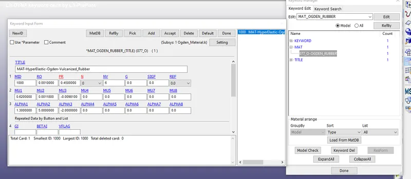
- Initially open the LS Dyna keyword file which is containing only the ogden material card, like shown in below image
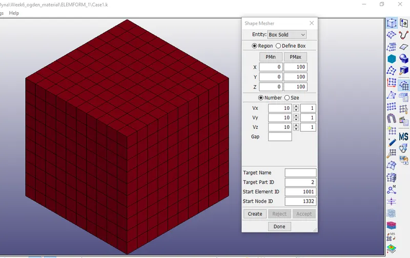
- Now we have to create a cube of 10*10*10 mm cube with 10 elements on each face
- inorder to create the cube go to element and mesh>shape mesher>box solid
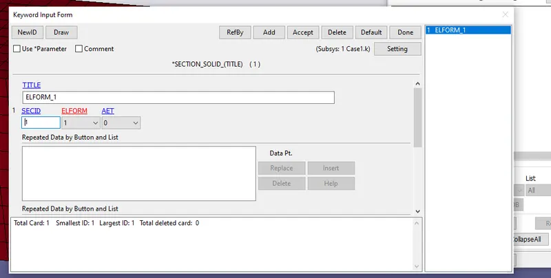
- Create a section card for solids with element formulation=1, -1, 2,-2 for case1,2,3,4 respectievely
- Now assign the section card and material card to cube
- To perform a tensile test we need to fix the cube on one side and apply the displacement load on the other end
- Create few node sets as defined below
- Select the nodes from one face and restrict them in global x direction
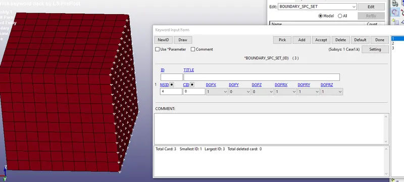
- Now select the nodes in global z direction and constrain the DOF in y direction
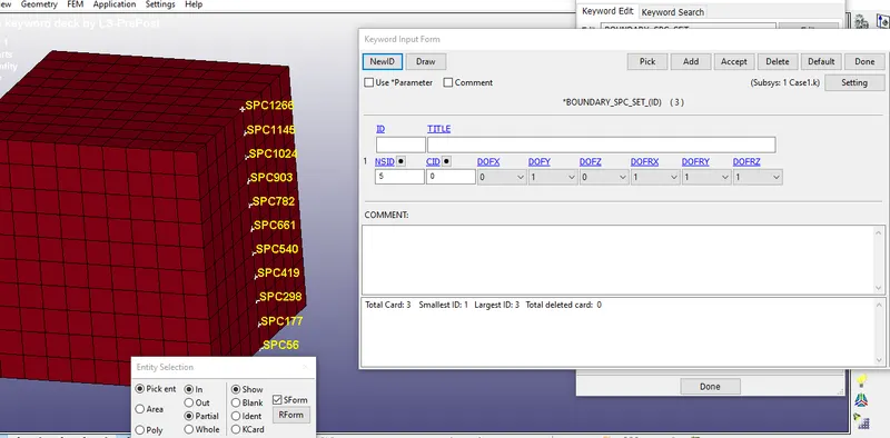
- Now select the nodes in global Y direction and constrain the DOF in Z direction
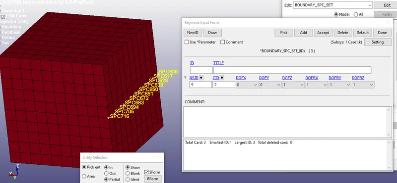
- Now create node set id for prescribed motion set like shown in below image
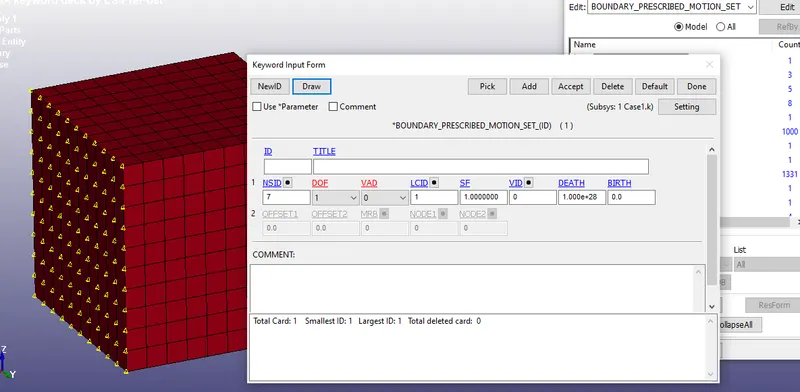
- We know that the stretch ratio should be 5
Stretch=1+engg strain
5=1+(Change in displacement/10)
Displacement=40mm - We have to specify the displacement as 40mm, in order to give the displacement define a load curve
- Go to keyword manager>Define>curve
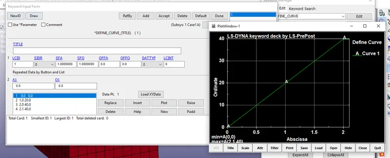
- Now assign this load curve to prescribed motion set card
- Now inorder to solve this problem using implicit solver, we need to create few implicit cards mentioned below
- go to keyword manager>controls>create Implicit_auto, Implicit General, Implicit solver,Implicit solution cards
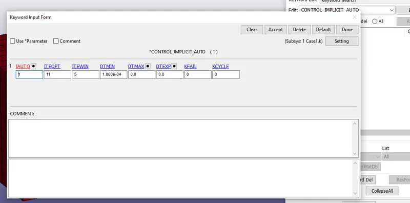
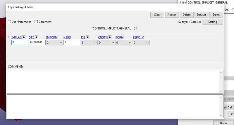
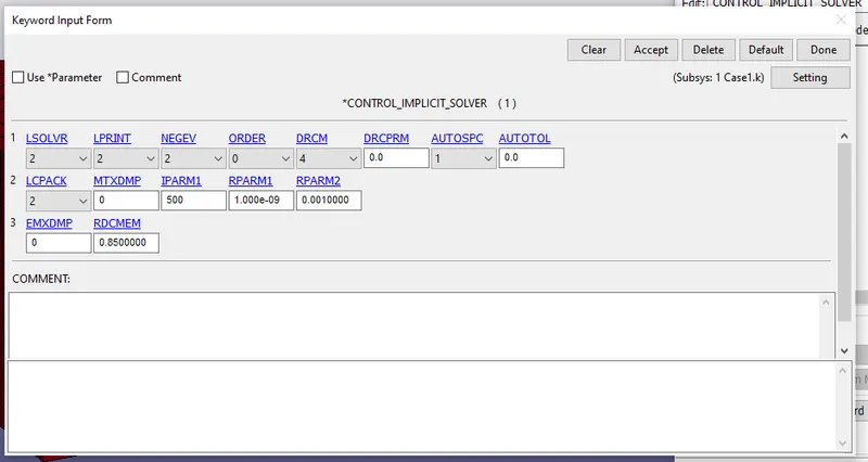
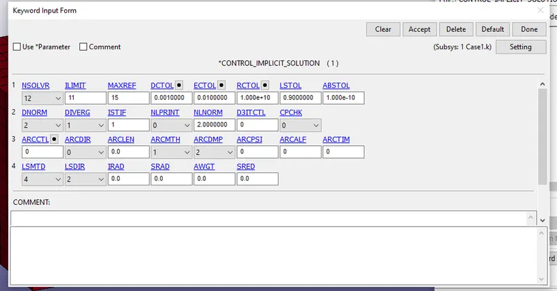
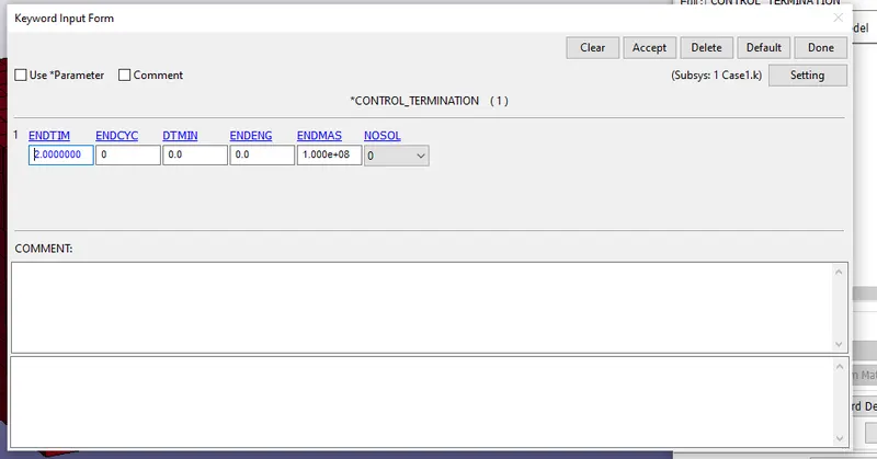
- Create a termination card in order to run the simulation till 2 second
- Now create database cards like ASCII and Binary to get the required output
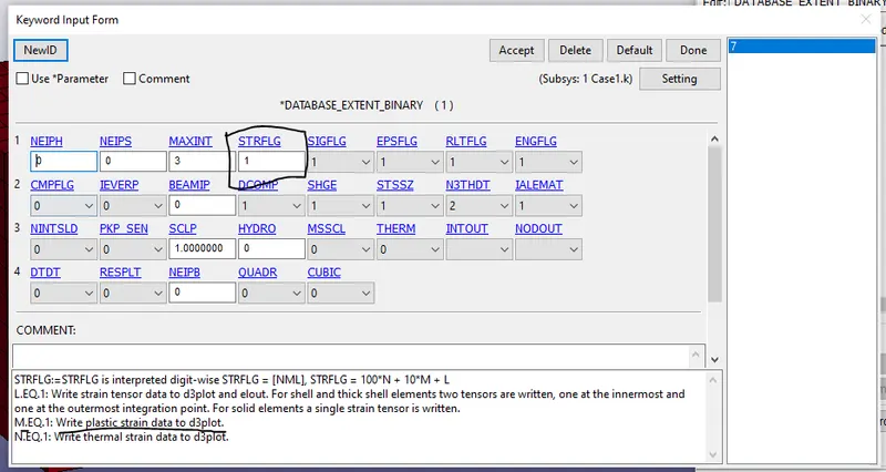
- Create Binary extenet card and set the STRFLG=1 as mentioned above in challenge
Output:
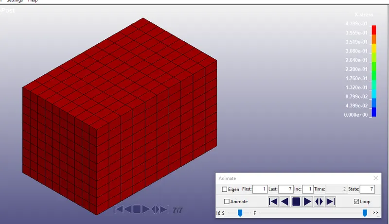
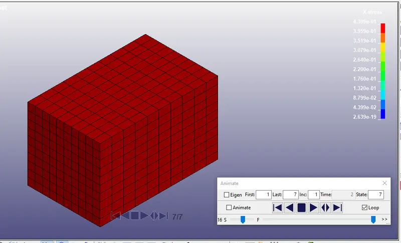
Case 1(ELFORM=1):-
- X-stress
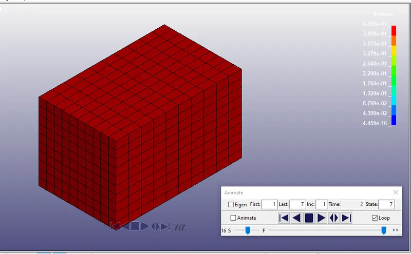
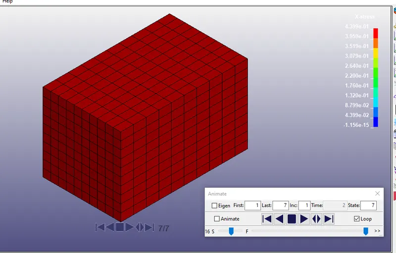
Case 2(ELFORM=-1):-
- X-stress
Case 3(ELFORM=2):-
- X-stress
Case 4(ELFORM=-2):-
- X-stress
- The output what we get in post fringe are True stress and True strain values
- Inorder to calculate the stretch ratio we need to caluclate Engg stress and strain using the formulas
True Stress:- `sigmat`=`sigmae`*(1+`epsilone`)
Engg stress:- `sigmae`=`sigmat`/(1+`epsilone`)
True Strain:- `et=ln(1+epsilone)`
True Stress:- `epsilone=((exp epsilont)-1)`
Stretch ratio:- `lamda=1+epsilone` - Initially from history, plot the graph for an element true X-stress and strain(lower ipt X-strain) to all the cases(plot the graph for same element to all the cases)
- Save the plot with required interpolate points
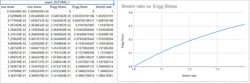
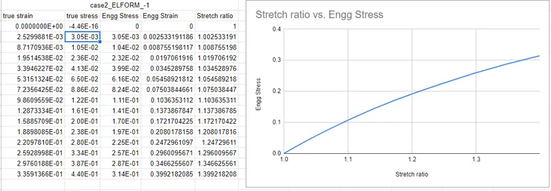
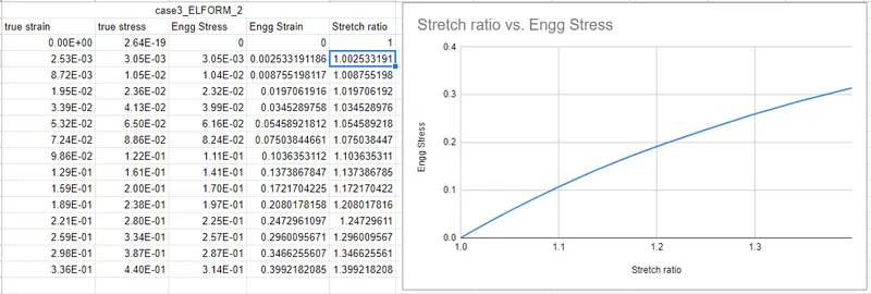
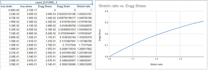
- import the true stree and strain value to an excel sheet and calculate Engg stress and strain and Stretch ratio
- The graphs Engg stress VS Stretch ratio is shown in below images
- Case1
- Case2
- Case3
- Case4
CONCLUSION:
- Usage of different formulations will effect our computational time, in this because we do not have much variation.
- If the model would have been large or complicated we could have seen the computational time difference for each element formulations