Week 6
AIM: To establish the connection wherever is required in given component
PROCEDURE:
Step 1:-
- The given is containing only FE model, so need of performing TOPO and geometry checks
- Firstly started the connection from the door's supporting to the B pillar portion
- Create points by On COG method from TOPO deck > Points > On COG
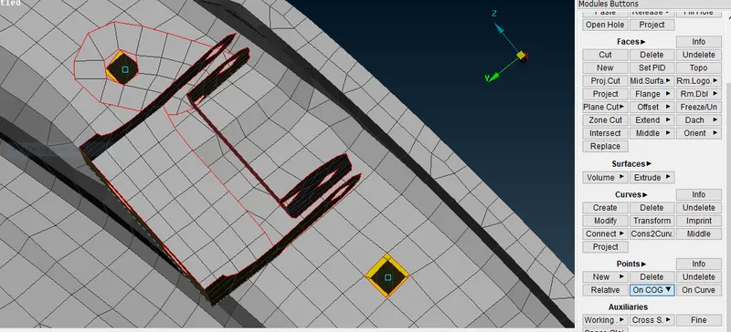
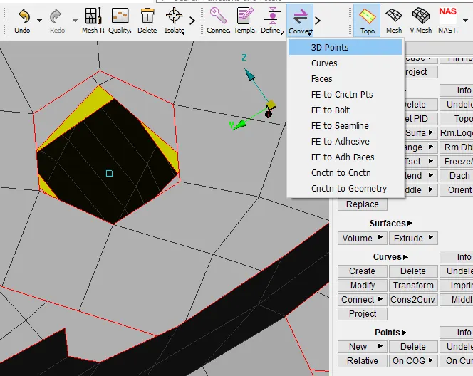
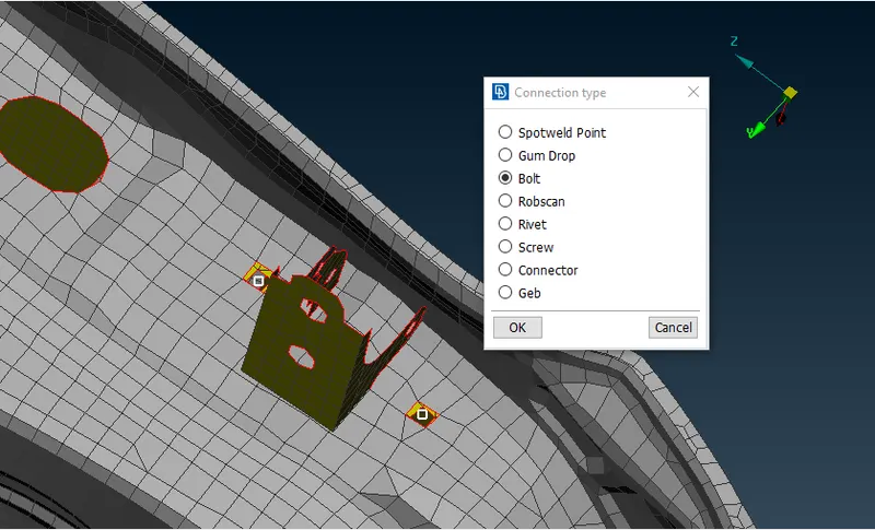
- Convert the 3D points to Bolt
Step 2:-
- Go to convert manager in order to define the Bolt definition
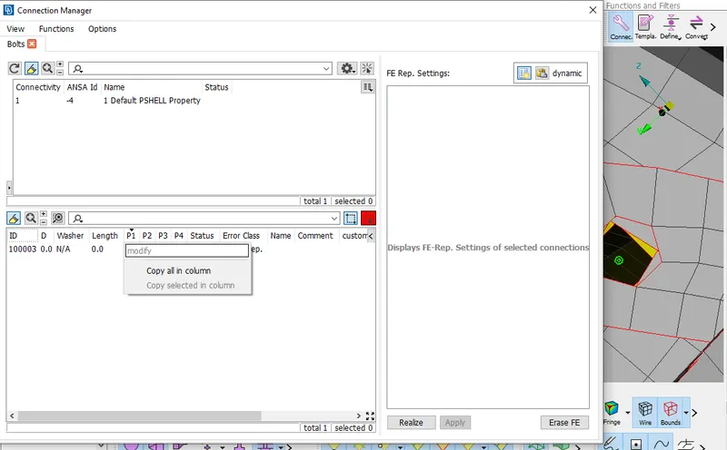
- Select the different parts which are associated with the connection one by one
- use function key F1 to assign respective parts to the connection
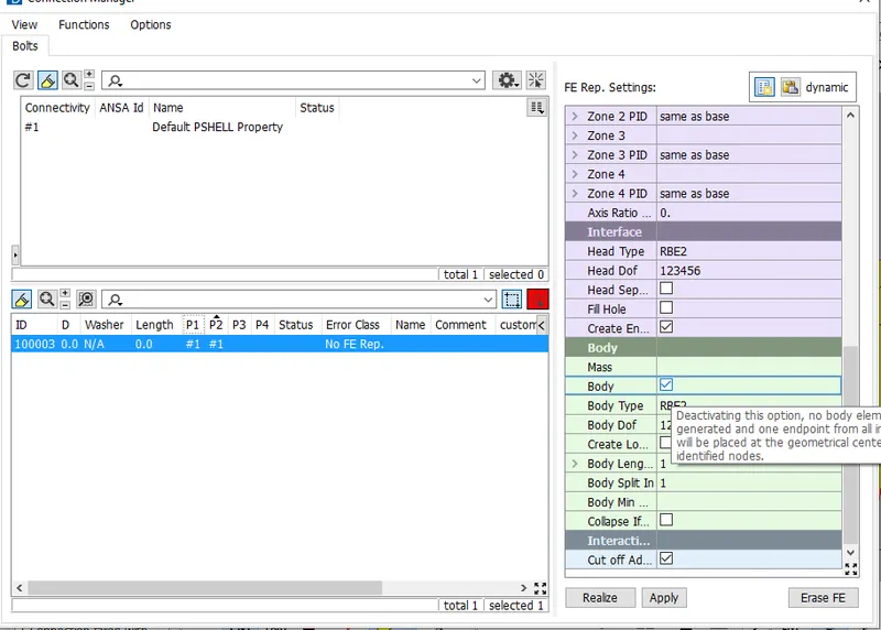
- In the above image you can see the body option is enabled, this will result in representing the bolt's body
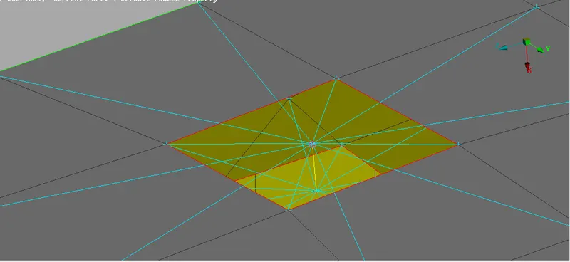
- Yellow line in the above image represents the Bolt body
- If the body option is disabled then connection representation will be as shown in below image, it will form a cluster connection
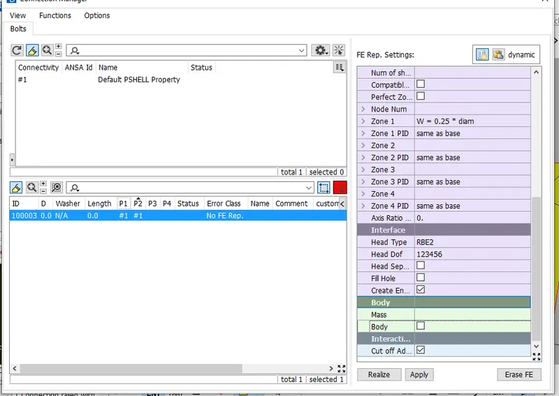
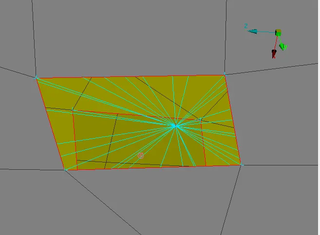
- Both the above bolt representations is correct.
Step 3:-
- Other way of creating the connection is by using RBE2 by many node option from nastran deck
- This method can be used where you can see only few portion of the connection
- Steps followed in building RBE2 connections are
- Select the slave nodes , master nodes and Finish the coneection
- Slave nodes are the nodes which depends on the behaviour of Master nodes
Step 4:-
- There are many types of selecting the nodes for creating Rigid body element
- First one is by manually selecting all the nodes one by one , which is very time consuming
- Next is using loop method , where just by selecting one element all the required nodes will be selected in one shot
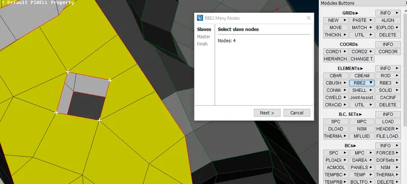
- In the above image using the loop method in single shot all the required 4 nodes are selected
- In order to represent the washer connection too, it is always better to go with nodes mode, where you will be selecting respective entities instead of nodes as shown in below image
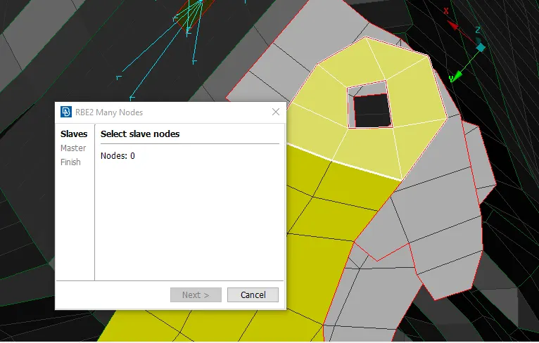
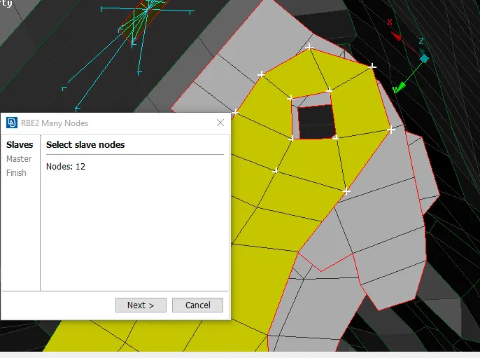
- In the above image the perimeter of the hole nodes are selected which is the better way of representing the Bolt along with the washer
Step 5:-
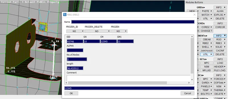
- When creating the hinge portion, use RBE2 by two node method
- Just connect the two node of the rigind body element in the support
- Now go to INFO option and relese one Degree of freedom, with respect to which the door has to rotate
- In this case the door should rotate in Z direction(by refering vehicle co-ordinate system)
- go to INFO click on the hinge connection and change CM(DOF) from 123456 to 12345
- Because 6 is the Rotational degree of freedom with respect to Z direction
Step 6:-
- Next is to assign connection for handle by RBE2 many node method
- Connect the two RBE2 by other Rigid body element from the centre
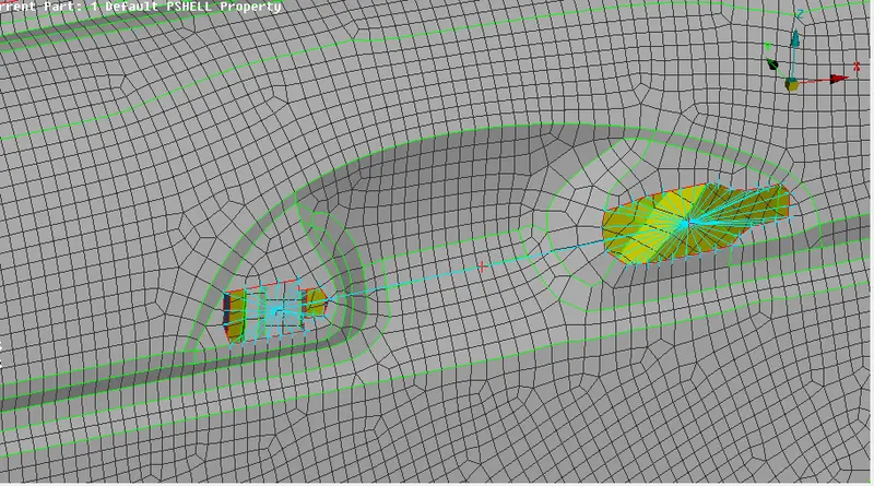
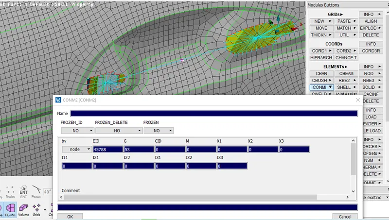
- On the handle's master node assign the mass by CONMi>CONM2> Nodes
- Here the default mass representation unit will be in TONNES, keep that in mind and assign your mass
Step 7:-
- Next is to reperesent weld connection
- First create Points and convert the points into spot weld point
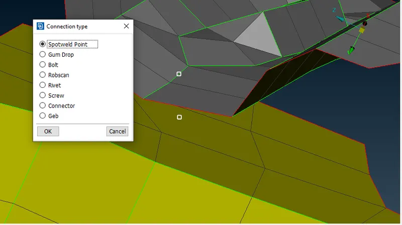
- Define the point by using connection manager
- Select the respective parts P1 and P2, create PSOLID ID for the spot weld
- Important is to keep FE Element type as RBE3-HEXA-RBE3 for this kind of weld
- In this type the corner nodes will act as master node and middle one will be the slave node
- Carry the same procedure for the places where spot weld representation has to be done
Step 8:-
- After finishing all the Bolt and spot weld connection next is to represent the damping(weather strtip) for the glass
- Use feat2curve option and extract the curve
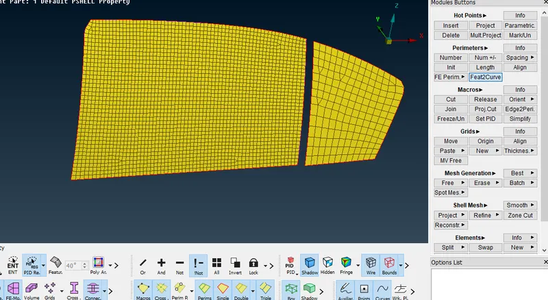
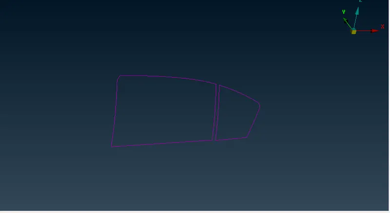
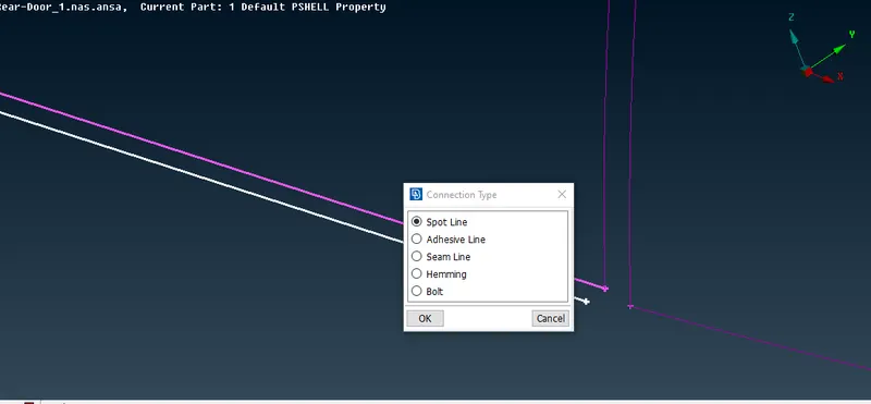
- Convert the curve into Spot line instead of Adhesive line, because adhesive line's motion will be restricted in all the direction
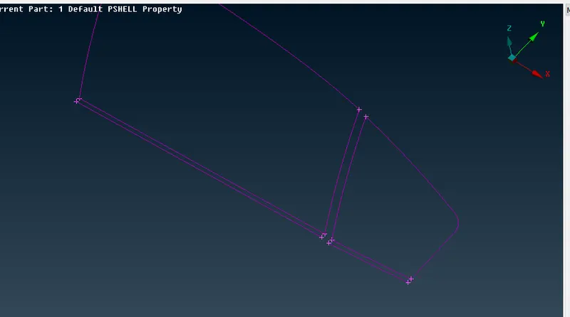
- The bottom part of the glass will have weather strip in both sides in order to represent the same, the bottom curve will be transformed in respective direction with some distance
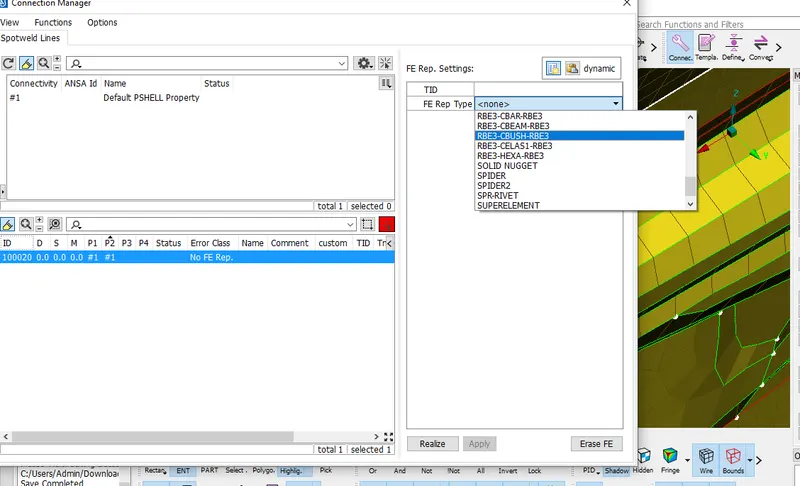
- Define the curve in connections manager by keeping the FE emelent type as RBE3-CBUSH-RBE3
- Select the respective parts P1 and P2 and give the needed spacing
- Define the CBUSH ID(SHIFT+?) also for future reference
Step 9:-
- Perform Step 8, arround the body because to represent the rubber strip running through out the body
- The CBUSH representation will have local co-ordinate system, in order to change all the CBUSH element to vehicle co-ordinate system
- As we defined the CBUSH ID previously, we will be using the same here and selecting all the elements right click and modify
- change the orientation fro with Vector to With cord and chnge CID to 0(zero)
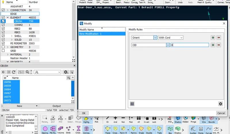
- Now all the element will be alligned according to Vehicle co-ordinate system
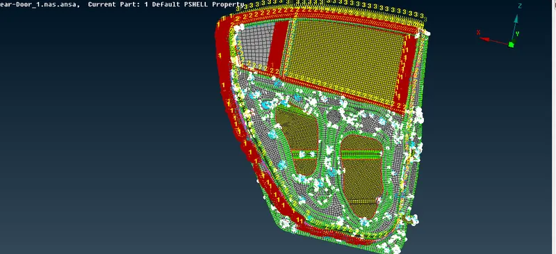
- Final result is shown in the below image
LEARNING OUTCOMES:
- Learnt how to analyze diffrent connection
- Understood Damping representation and alligning all the elements in same direction.
CONCLUSION
For the given model, the connections have been done.