Week 3
AIM : To check and clear the Geometrical error and to Mesh the given component.
Procedure:
- After importing the model to ANSA using property manager seperated different parts
- I have seprated the part as Bottom Hood(thickness=0.75mm), Top Hood(thickness=0.75mm), Middle part(thickness=1.2mm)
- Right click on Bottom hood from property manager select show only, so that only one part can be accessed seperately
- Do a Topology clean up and perform a geometry check
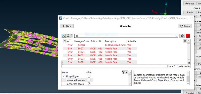
- Right click on the errors and auto fix
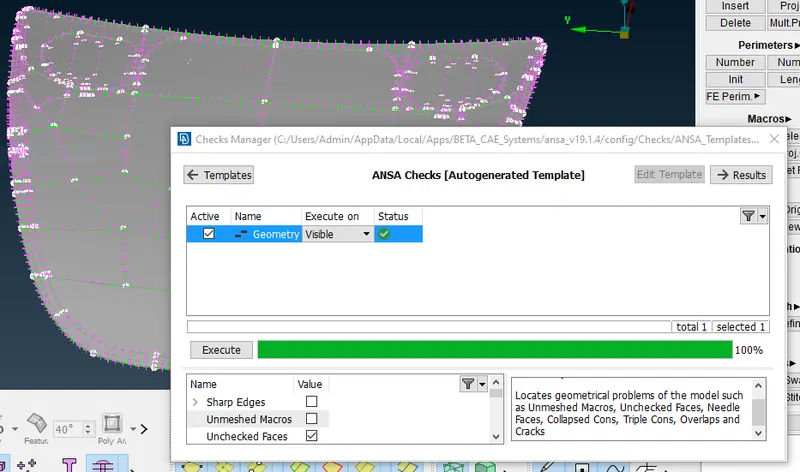
- After fixing all errors proceed with further operation
- Next step is to extract the Mid surface, there are two ways to do the same , auto and manual mid surface extraction
- For manual mid surface extraction, measure the thickness of the body and offset the face exactly to the middle
- In auto mid surface extraction select >skin for sheet metal components, >casting option is used to solid components
- I have used Auto mid surface extraction for Top and Bottom hood, because there was more crucial faces, in order not to miss any surface , used the auto mid surface extraction
- Have used manual mid surface for middle part, because the body was not much complicated
- Diffrence between this two extraction methods are, in auto mid surface extraction the body will be deleted automatically, in manual mid surface extraction the body can be retained
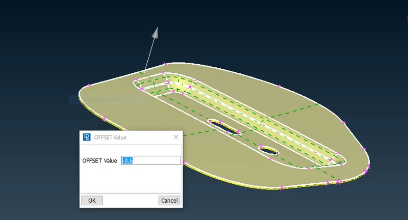
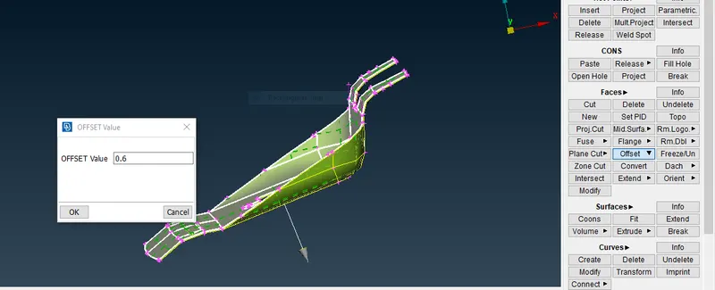
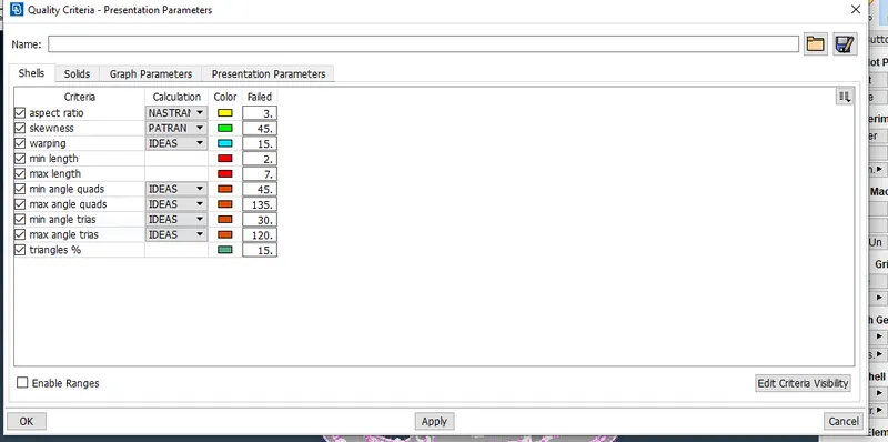
- after extracting the mid surface, define the meshing parameter and assign the mesh quality criteria as given
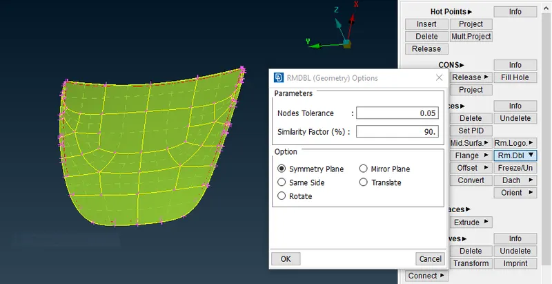
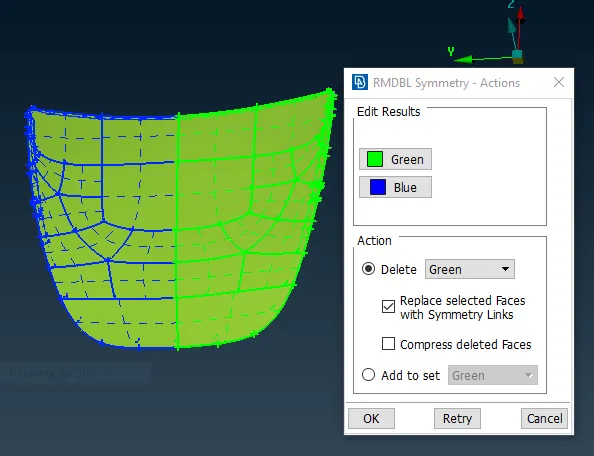
- Use Remove Double(Rmv dbl) option for symmetric component so the only one side of the component can be worked.
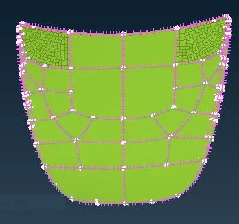
- Moving to mesh module and give the element length as 5mm and create the mesh using best mesh generation method
- Check for the quality criteria and try to fix the errors by split, reconstruct, fix quality etc
- after meshing save the mesh as new Part ID by using "Set PID" option and give the name, thickness and material ID
- Do the same procedure for all the parts
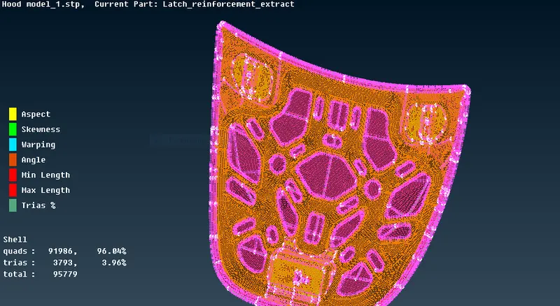
- Make sure there are no OFF elements
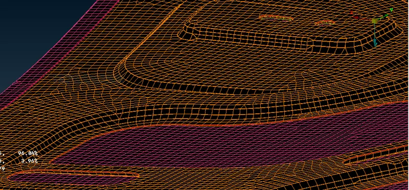
- after succesfully meshing all the parts assign the thickness to the mesh
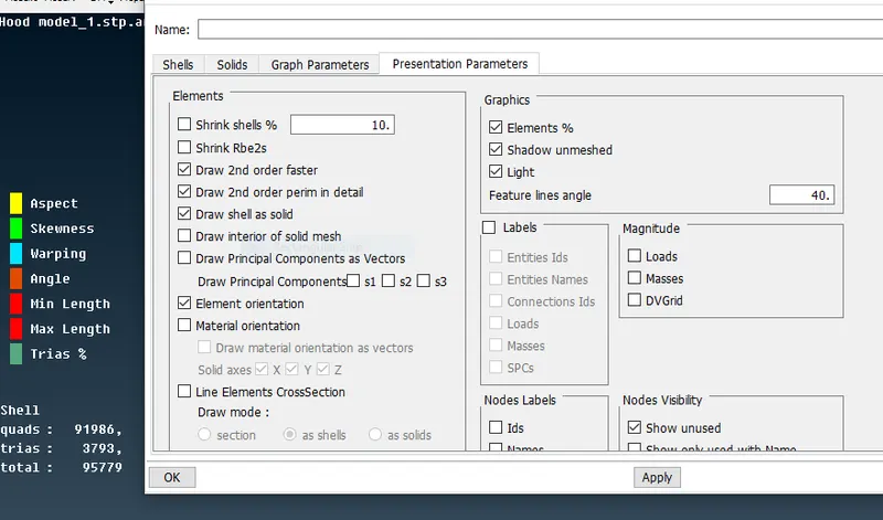
- assign the mesh thickness by going to Quality criteria>Presentation parameters>Draw shell as solid
Learning Outcomes:
- Learnt how to use remove double option and how it is useful for symmetric components and understood its time saving which is a very important factor
- To assign thickness
- understood the need of SET PID
- understood why we have to give thickness in Property ID bar
- got familiar with commands like poj cut, split,slide, mark/unmark, reconstruct
Conclusion
Got to know the diffrent options that are available to rectify the errors,
Many challenges like this will build the confindence of students towards the software.