Week 4 -Wire Bending Challenge
OBJECTIVE:
- Set up the model for wire bending with different materials
- Compare the results with different cases
Steps:
Import the material
- First open the ansys workbench and import the materials
- Go to Engineering data>Engineering Data sources>Genral Non linear materials
- Select Copper alloy, Magnesium Alloy, Aluminum Alloy non linear materials
Import the Geometry:-
- Import the geometry from saved location
- Open the model in space claim and check for any abnormality
- In space claim we can edit the model to our requirement
Set up the model:-
- Open the Mechanical workbench for model set up
- Initially rename the geometry for convinience
- Assign the wire material as copper alloy,Magnesium alloy, Aluminium Alloy for case 1,2,3 respectievly
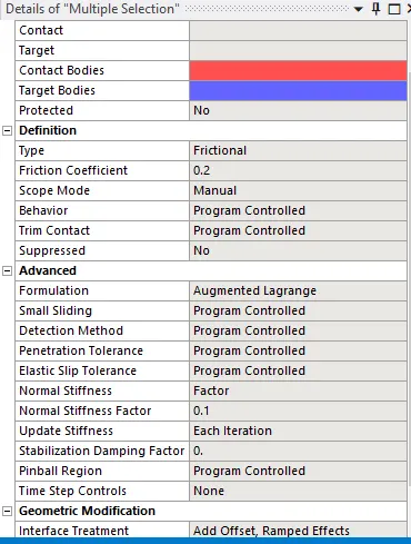
- Delete the default contact between wheel , wire and lever
- Now create connection between Wire-Lever and Lever-Wire
Create Joint:-
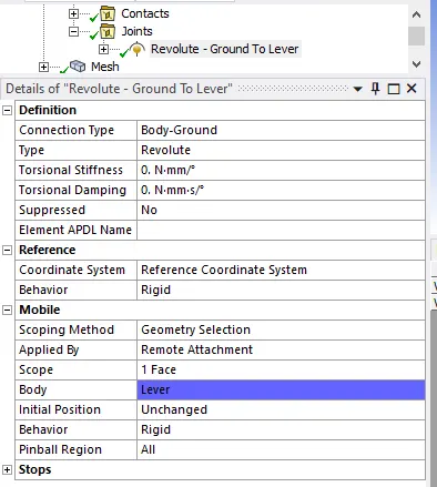
- Define Joint load for lever like shown below
Mesh:-
- Mesh all the bodies with element type tetrahedron
- Perform face sizing of 2.2mm for contacting faces
- The fillet in the wheel , where more amount of stress might take place, so it is better to refine mesh
- Create a new co-ordinate system near filleted region,
- Using the newly created cordinate system, create sizing of element size 0.8mm
Type=Sphere of influnce
Sphere centre=Newly created cordinate system
Sphere radius=7mm
Analysis Setting:-
- Number of steps=8
- For step 1
Solver type=Direct
Weak springs=Program controlled
Large deflection =ON
Auto time-stepping=ON
Initial time step=0.1
Minimum Time step=0.01
Maximum Time step= 0.2 - For step 2 to 8
Auto time stepping=ON
Defined by=Time
Carryover time step=ON
Minimum time step=0.01
Maximum time step=1
Define Load:-
- Define a fixed support for the Wheel
- Define Fixed support to the end of wire
- Define Revolute joint with DOF Z
Magnitude=tabular data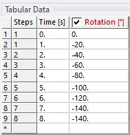
Output Request:-
- Note down the results for Equivalent Stress, Equivalent Strain and total Deformation
- Note down the results for all the three cases
Results:
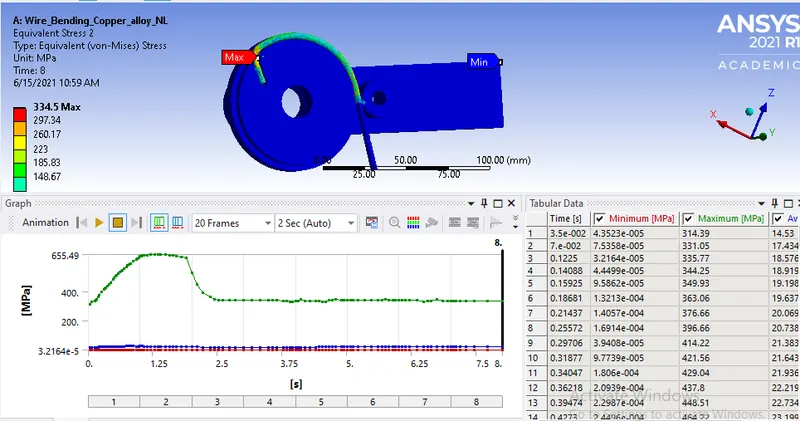
Copper Alloy:-
- Equivalent Stress
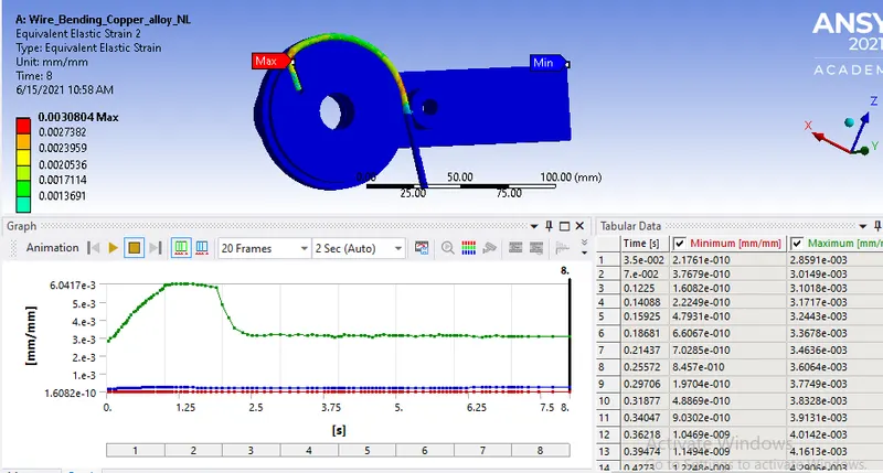
- Equivalent Strain
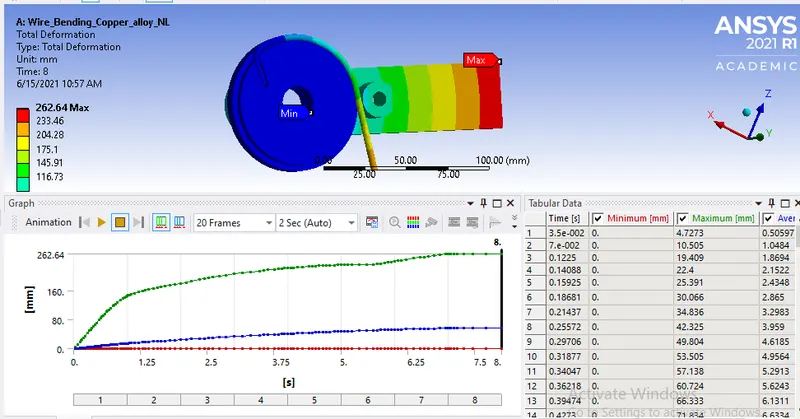
- Total Deformation
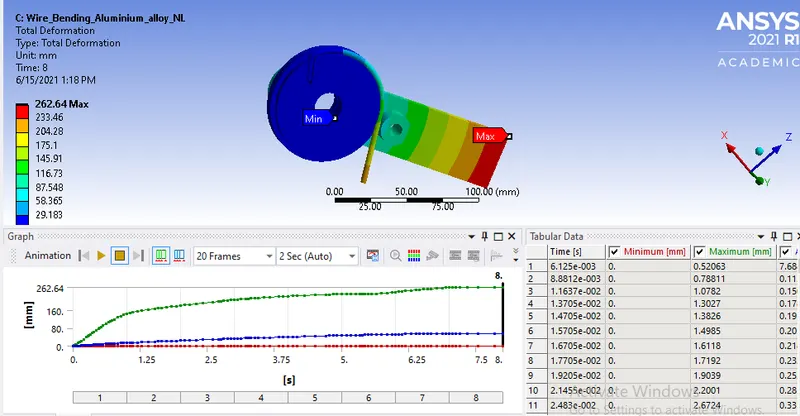
Aluminum Alloy:-
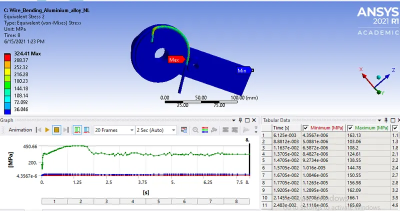
- Equivalent Stress
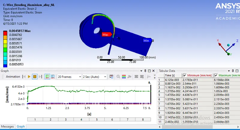
- Equivalent Strain
- Total Deformation
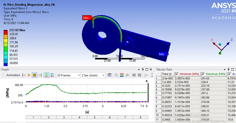
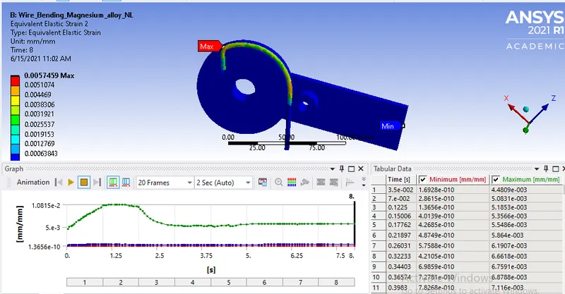
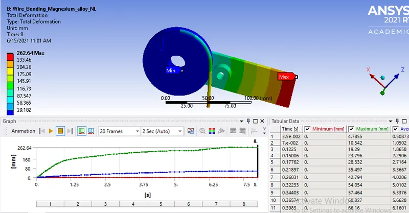
Magnesium Alloy:-
- Equivalent Stress
- Equivalent Strain
- Total Deformation
-
Material Equivalent Stress(Mpa) Equivalent Strain(mm/mm) Total Deformation(mm) Copper Alloy 334.5 0.0030804 262.64 Magnesium Alloy 257.92 0.0057459 262.64 Aluminium Alloy 324.41 0.00458577 262.64
CONCLUSION:
- We can see the results from above table, the highest stress generated in all the cases are at wire
- The highest stress generated in copper alloy
- The lowest strain generated in copper alloy
- Total deformation is same in all the case