Project 1
AIM: To extract mid surface and mesh the given model according to the quality criteria
PROCEDURE:
Step 1:
- First step is to perform TOPO on the model as soon it is imported into the software, in order to clear the transition error
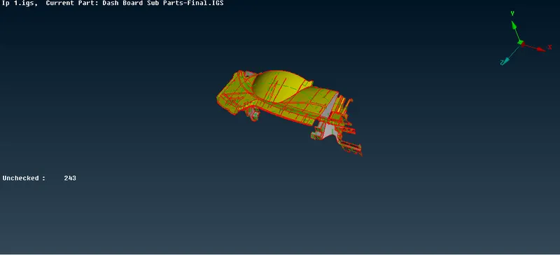
- Below image represents the model befor performing TOPO, it is observed no faces are stitched together.
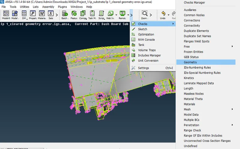
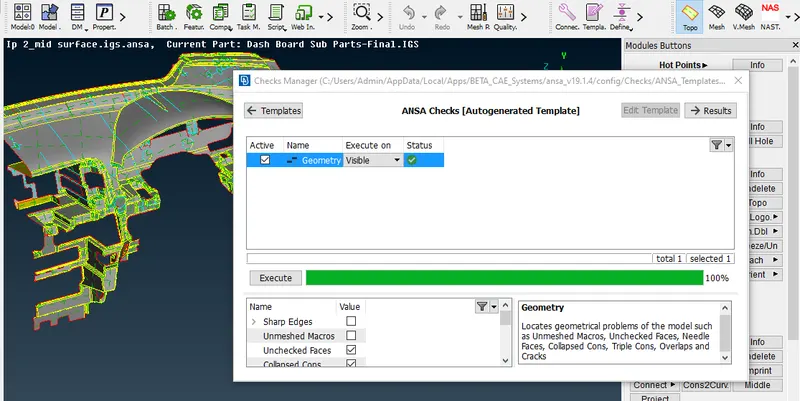
- Check for the geometry error by Check>Geometry>Execute
Step 2:-
- If any geometry errors are found isolate it and fix the same either by auto fix or manually fix all the errors
- Check for collapsed face, single cons, triple cons and fix all the error
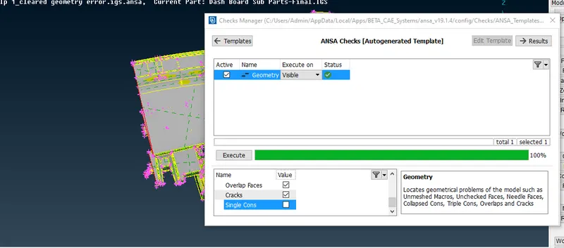
- In this case the model given is cut into half, so single cons are present, neglecting those cons and check for the geometry error
Step 3:-
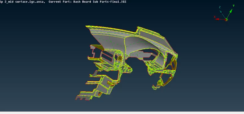
- Afetr checking the model for error next is to extract the mid surface for the component
- First measure the thickness of the model in many instances
- offset the surface giving the offset value as half of the measured thickness
Step 4:-
- Once the mid surface extracted go to set PID and assign thickness and give an user defined name
- When trying to extract a mid surface keep the selection in feature mode, so that the whole feature with same thickness will be selected in single shot
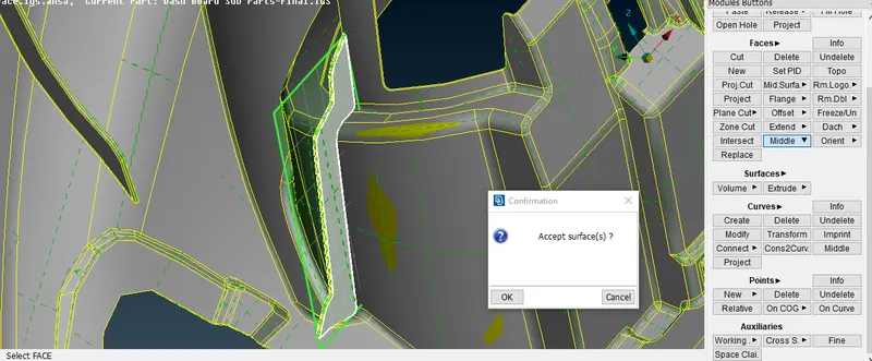
- once the main parts mid surface is extracted , start extracting the mid surface for features like Ribs?(stiffners) and Dog house
- Use Face middle or Face Offset option to extract the mid surface
Step 5:-
- Once the mid surface of ribs are extracted connect the same to the main parts mid surface using extend option
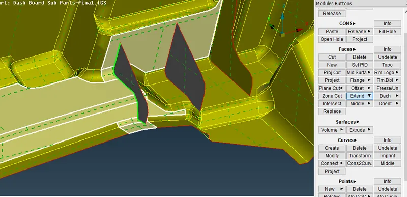
- After extending the ribs, take mid surface of dog house feature
- Offset the feature from outside by giving a small value
- The double of the offset value should be assigned as thickness for the mid surface
- For example if the feature is offsetted with a value of 1mm, then assign the mid surface thickness as 2mm
Step 6:
- After Mid surface extraction performed check for all the geometry errors , except for single con and triple cons
- Because the mid surface perimeter always are single con and due to extend operation performed triple cons are also formed
- Below image represents the geometry checks of Mid surface
Step 7:-
- Once the Mid surfae is ready, next move to mesh module deck
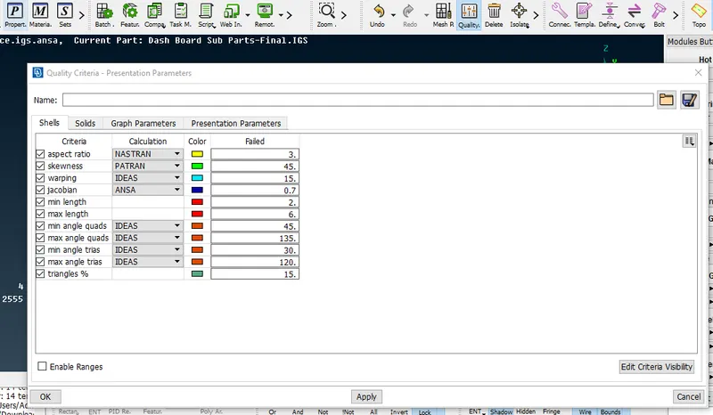
- Give the mesh parameter value and Quality criteria
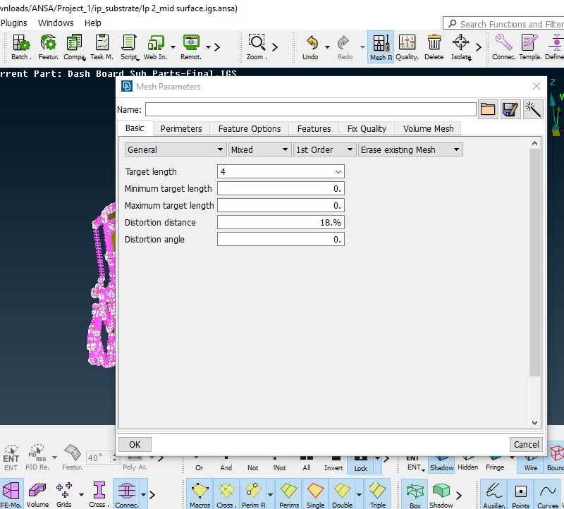
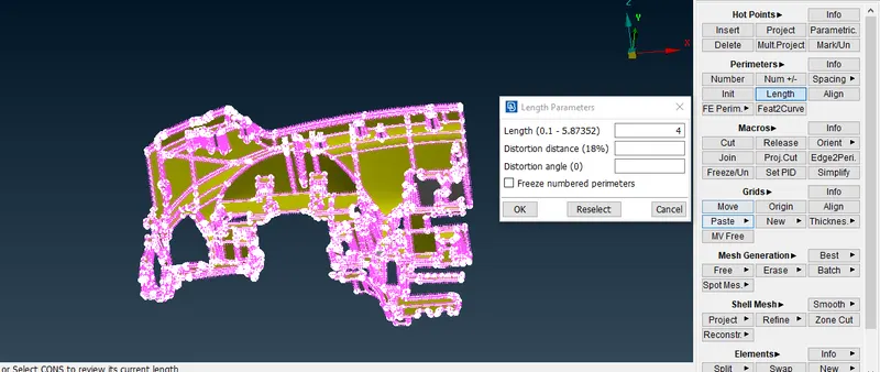
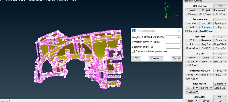
- Assign the Macros and Perimeter length
Step 8:-
- Start Meshing every region seperately and fix the off element by reconstrution, smooth or split options
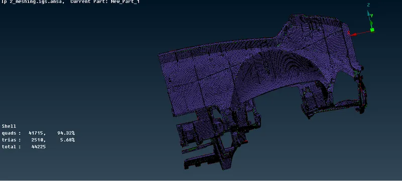
- mesh all the regions and try to fix all the OFF elements present
- In the given model , the OFF elements due to triple cons are acceptable.
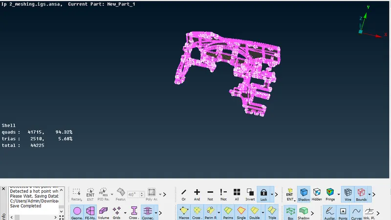
- The above image is the final representation of fully meshed part
Step 9:-
- Finally assign the thickness to the mesh by Quality criteria> Presentation parameters> enable "Draw shell as solid"
- The given thickness in property ID will be assigned to the respective feature
LEARNING OUTCOMES:
- Understood the different cases of error which might occur in damaged region
- understood how to fix unchecked faces error
- Imporatnce of assigning the PID to extracted Mid surface
- Understood the importance of meshing region by region
CONCLUSION:
- The given Model is fully meshed and assigned the thickness to the same
- The final model drive link is attatched below, please go through the same
- https://drive.google.com/file/d/1_K3YQcFzyNwj-zivO70LauOmEHHo8ZM6/view?usp=sharing