Week 3 Sheet metal Bending challenge
OBJECTIVE:
- Set up the model for sheet metal bending with respective contact and loads defined
- Compare the results of different materials
- See the results for same material with different mesh size and different friction co-efficient
STEPS:
Import material:-
- First import the material from engineering data sources
- Import the all the required materials for the analysis
- Import Aluminium alloy and duplicate it and rename it as aluminium alloy 1199
- Change few mechanical properties like Youngs modulus=62000Mpa; Yield strength=140Mpa;Tangent Modulus=209.46
Import geometry:-
- Import the model to the software
- Open it in space claim and look for any damage in the model
- If there is no issue with the model , open it in mechanical module and start setting up for analysis
Mechanical Module:-
- Update and enter the mechanical module
- Initially delete all the default contact
- Rename all the geometry for convinince
- First case assign the material as aluminium alloy 1199 to sheet geometry
Generate contacts:-
- Contact>Insert>Manual contact region
- First establish connection between punch and sheet,
Contact=Bottom faces of punch
Target=Top face of sheet - Establish contact between sheet and die
Contact=Bottom face of sheet
Target=Die face
Define contact:-
- For both the generated contacts , define the contact
Type=Frictional
Friction co-efficient=0.1
Behaviour=Assymetric
Formulation=Argumented lagarange
Normal stiffnes factor=0.1
Interface treatment=Add offset, ramped effects
Meshing:-
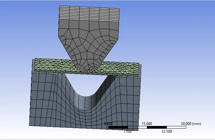
- Initially use sizing option for punch and die body with 4mm element size
- Do sizing for sheet with 2mm element size
- Perform sizing for Contact faces of punch and die with 1mm element size
- Before generating the mesh, Only for sheet use tetrahedron element
Analysis Setting:-
- Create 10 steps for the analysis, apply the below settings for all the step
- Number of steps=10
Large deflection=on
Energy disipation ratio=0.1
Stabilization=Constant
Sover type=Direct
Define Load:-
- Define the displacement load for punch by selecting the top faces
- The punch has to bend the sheet and has to retrived back
- Static structural>Insert>Displacement
Type=Displacement
Defined by=Components
X=Y=Z=Tabular data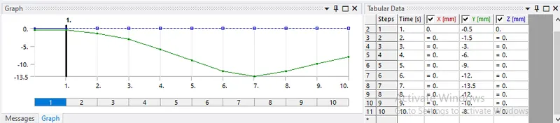
- Now define the Displcement load for sheet, the sheet should not move in global Z direction
- Select the side faces of sheet, insert displacement load
Type=Displacement
X=Y=Free
Z=Tabular data(Where all the Z values should be zero , in order to loction the motion of sheet wrt Z direction) - Define the displacement load for Die, The die should not move untill the bending happens
- Once the bending is done the, die should move in global negative z direction
- Select the bottom faces of Die to give the load
Type=Displacement
X=Y=Z=Tabular data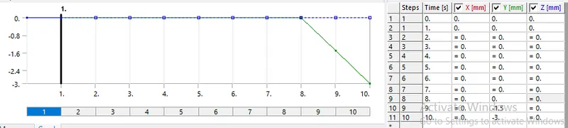
OUTPUT REQUEST:-
- Request the solution for von-mises Stress, Von-mises strain, Directional deformation with respect to Z direction , Von-mises stress for sheet
- Repeat All the steps and change only the sheet material for case 1
- For case 2, All the above steps remains same, change the friction co-efficient=0.19 for aluminimum alloy
- For case 3, Aluminium alloy as the material but the sheet mesh will be finer, i have used element size=0.75mm, so that the nodes did not cross academic limit
RESULTS:
Aluminium Alloy 1199:-
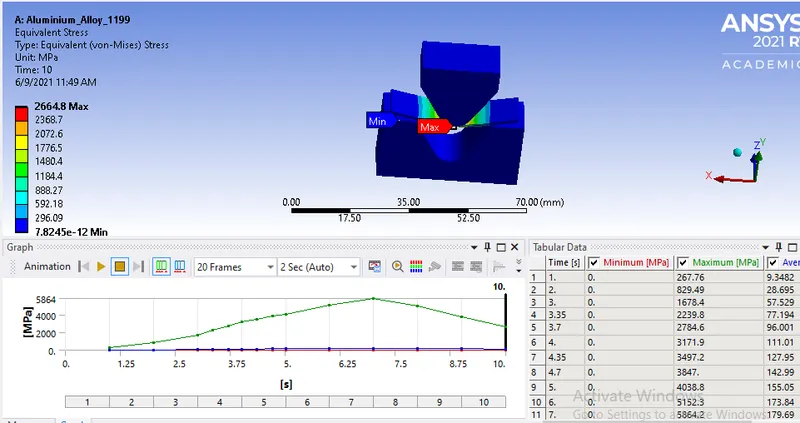
- Von-mises Stress
- Von-mises Strain
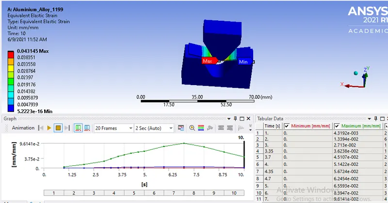
- Directional Deformation
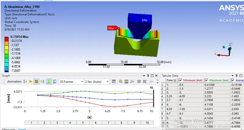
- Von-mises Stress for sheet
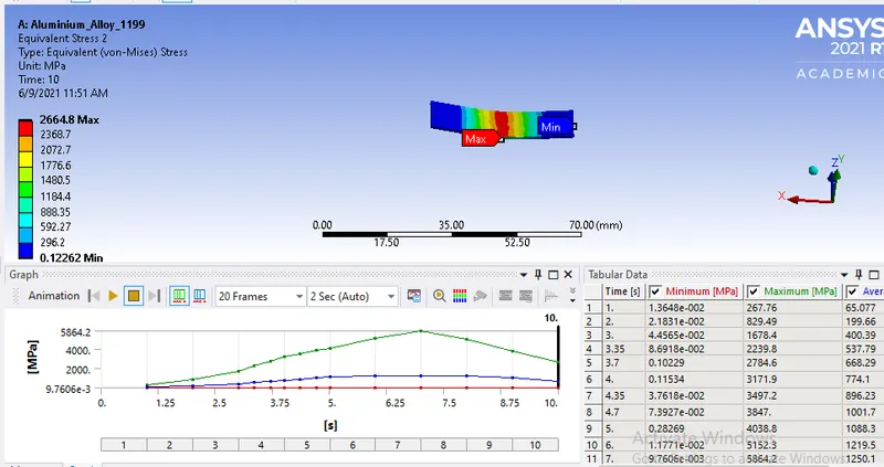
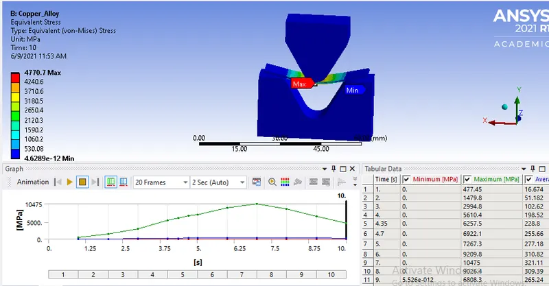
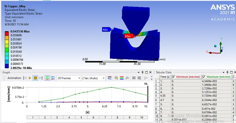
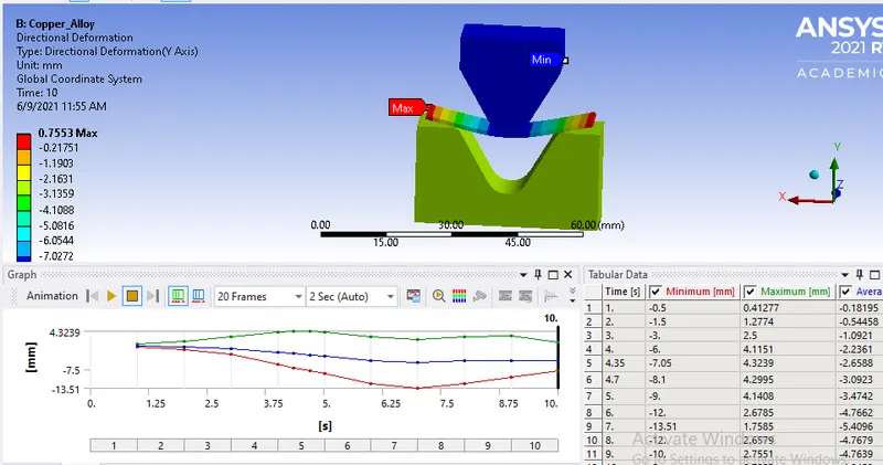
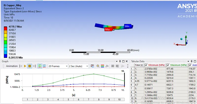
Copper Alloy:-
- Von-mises stress
- Von-mises Strain
- Directional deformation
- Von-mises stress for sheet
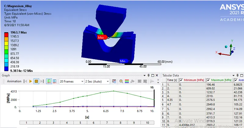
Magnesium Alloy:-
- Von-mises stress
- Von-mises Strain
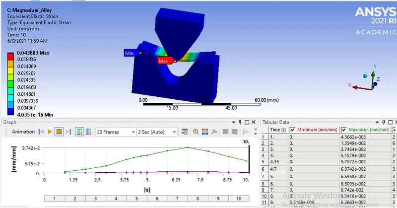
- Directional deformation
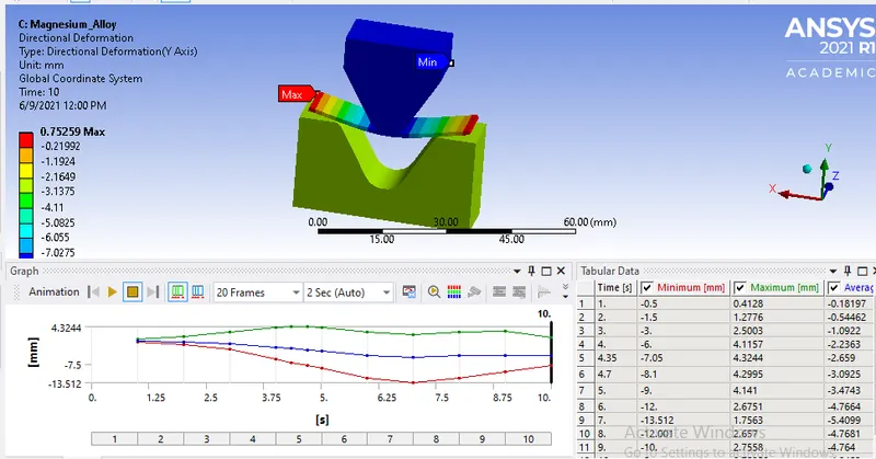
- Von-mises stress for sheet
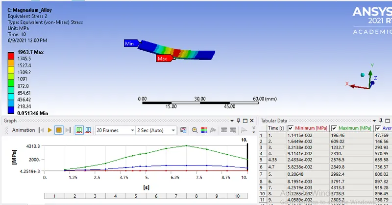
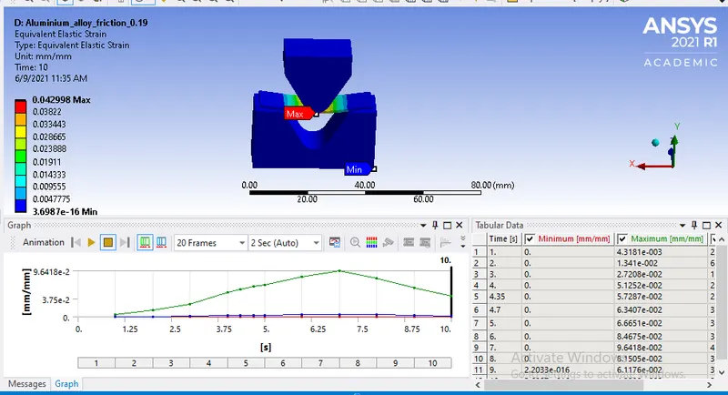
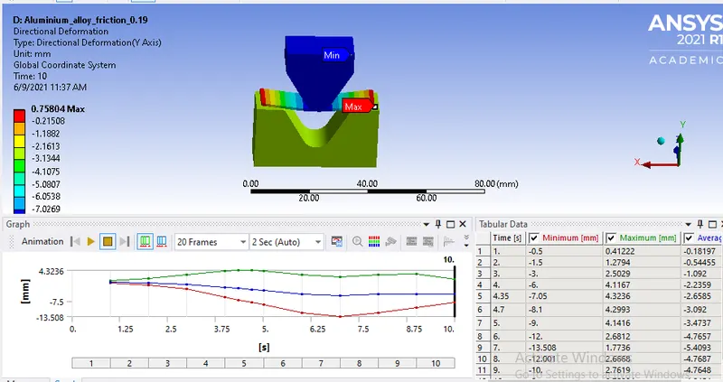
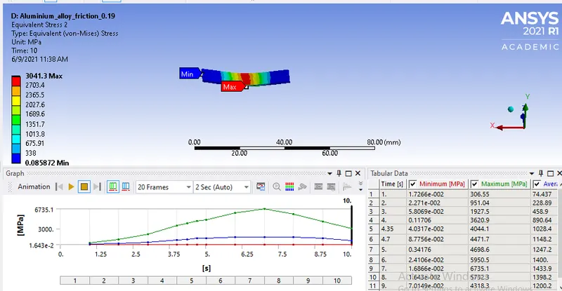
CASE 2:
Aluminium Alloy(Friction=0.19):-
- Von-mises stress
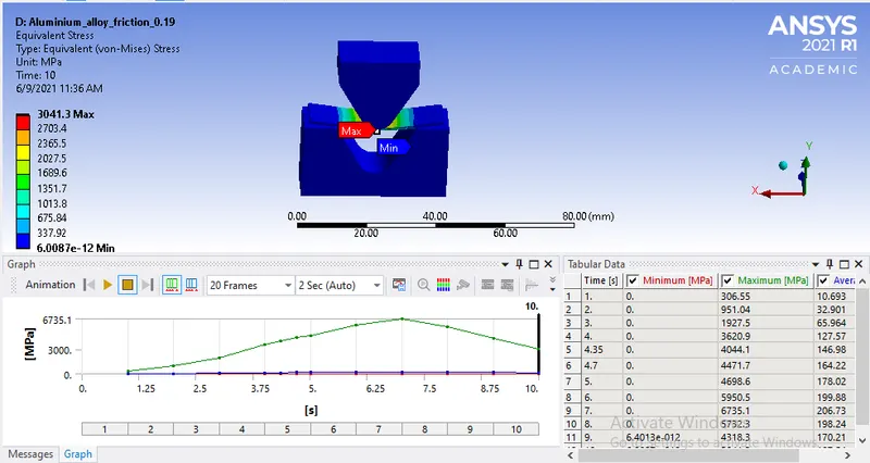
- Von-mises Strain
- Directional deformation
- Von-mises stress for sheet
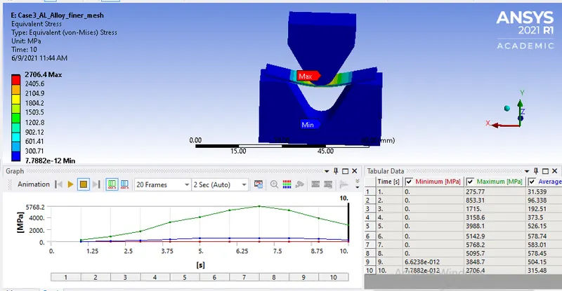
CASE 3:
Aluminium Alloy(Finer mesh):-
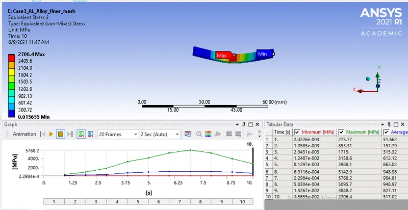
- Von-mises stress
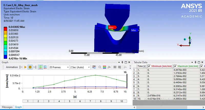
- Von-mises Strain
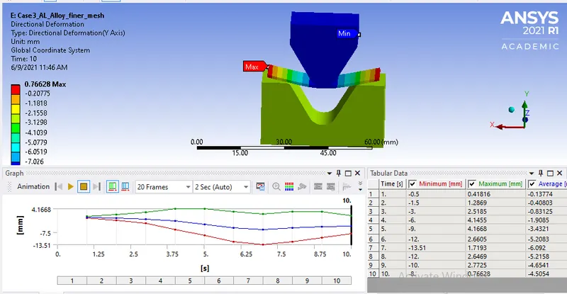
- Directional deformation
- Von-mises stress for sheet
-
Material Von-mises stress(Mpa) Von-mises Strain(mm/mm) Directional Deformation(mm) Von-mises Stress(Mpa) Aluminium Alloy 1199
2664.8 0.043145 0.75954 2664.8 Copper Alloy 4770.7 0.043536 0.7553 4770.7 Magnesium Alloy 1963.7 0.04380 0.75259 1963.7 Aluminium Alloy(friction=0.19) 3041.3 0.042998 0.75804 3041.3 Aluminum Alloy(mesh=0.75mm) 2706.4 0.043692 0.76628 2706.4
CONCLUSION:
- From the above results we can see the max von-mises stress of the model is equal to max von-mises stress of sheet, this tells us the maximum stress occurs in the sheet comparing whole model
- Copper alloy has the higher stress value among all the material, strain is almost equal to all the material
- Comparing Case 1 and 2, the stress is more in case 2, this shows that the friction co-efficient plays a major role. Higher the friction co-efficient higher the stress generated
- Comparing Case 1 and 3, the difference in the stress is 1.55% which is not much, but the differences between other factors are negligble