Week 9-Creation of 1D Connectors Challenge
AIM: To mesh given model and establish the mentioned connection to all the components
PROCEDURE:
Step 1:-
- Import the model to the software and take look at any geometry error if present
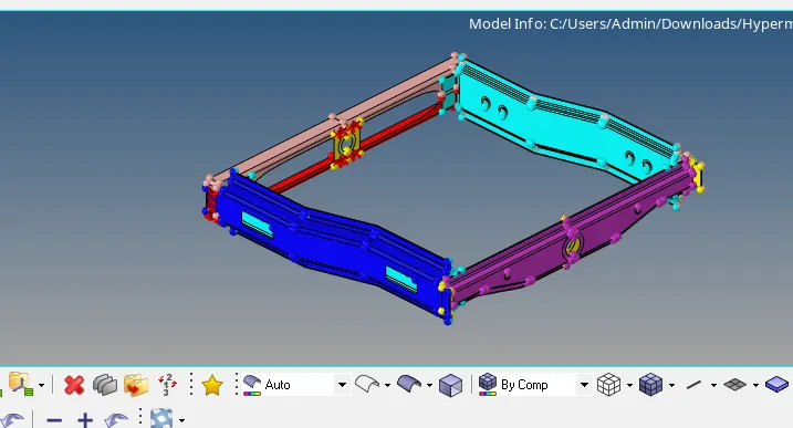
- Rear truss component has a geometry error, as shown in below image
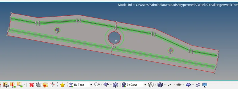
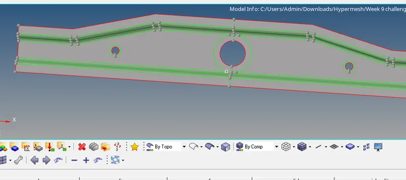
- In the above shown component edges are not stitched properly, so using toggle edge option it can be fixed
Step 2:-
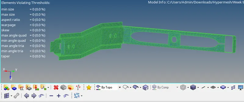
- Mesh the each component one by one with the given quality criteria
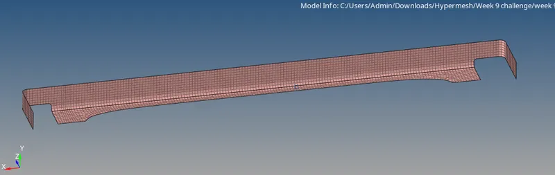
- Make sure the mesh flow is proper and satisfies the given quality criteria
- Mesh all the components with no quality failure, like shown in below image
Step 3:-
- There are few symmetric components like left rail 1&2 and right rail 1&2
- So mesh any one component and reflect it to the other component
- Inorder to reflect make sure there is a node exactly between them, duplicate of elements should be done
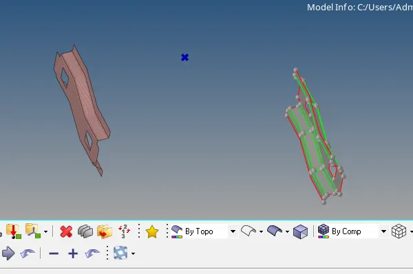
Before reflect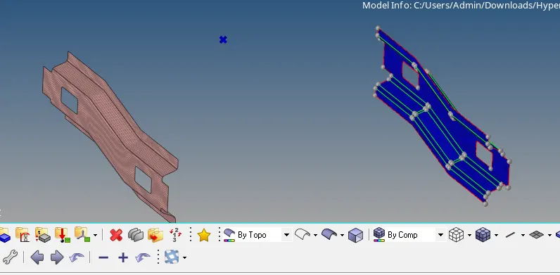
After reflect
Step 4:-
- Once all the components have been meshed wihtout any error, move to connectors
- First connection is between Right rail2 and front truss 1, connection type is seam-Quad(angled+capped+L)
- go to 1d>connectors>seam , change the type as quad angled capped L, give the tolerance value,cap angle value, select the components

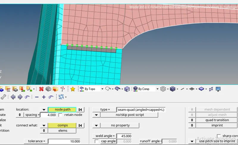
- Similarly all the other specified can be done by giving necessary values,
- other connections like bolt , seam rigid ,spring , quad, spot weld can be done under 1d>connector option
Step 5:-
- Once the connections are done , the mesh would been distrorted
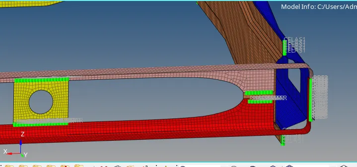
- make sure there are proper mesh flow and no quality errors in the model after the connections
- Remesh the parts wherever the mesh as distorted
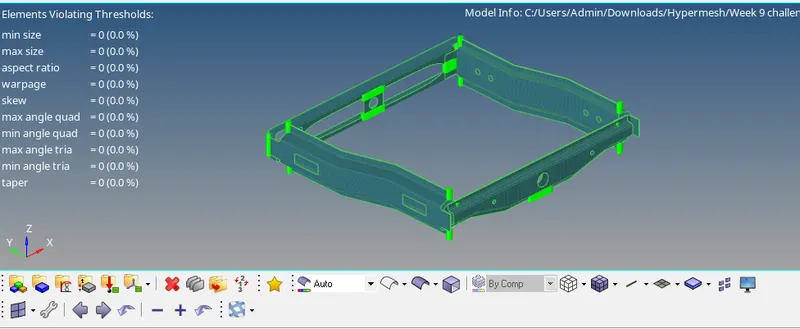
- The above image shows there are no quality issues after all the connections are done
CONCLUSION:
- Understood about the concept of diffrent connectors available
- Understood where to use connectors
- The given model is fully meshed and required connections have been done