Assignment 7-Side Pole Crash Simulation Challenge
OBJECTIVE:
- Intially set up the model for side crash, by creating rigid wall with given friction
- Create Interface with suitable parameters and friction = 0.2
- Check for the penetration and intersections
- Check the model by Model checker
- Create sections and intrusion in mentioned place
- Create respective output blocks
Steps carried out:
Check for unit system
- Open the 0000.rad file in notepad and look for the unit system used

- We can see the unit system used in themodel from above picture , same will be used in our simulation
Create interferance
- We have to create type 7 interface with suitable parameters
- The below image shows the type 7 interface card
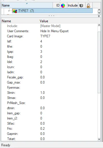
- In this card mention the fric value as 0.2
Penetration checks
- Now we have to check the groups(Interface) for penetration or intersections
- Go to tools>Penetration Check>Select all the groups>Check
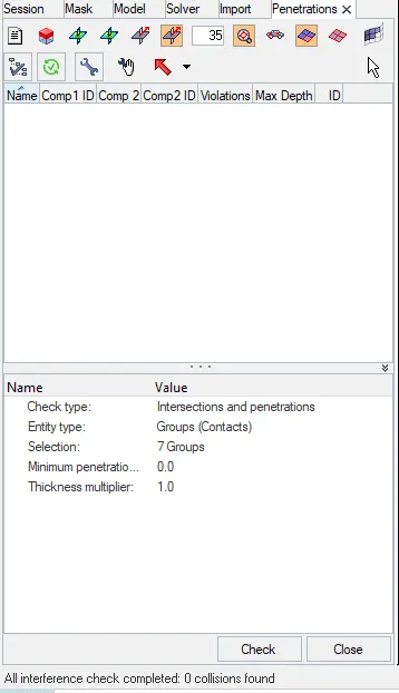
- In this case there is no Collisons found, so we can carry on next steps
Rigid body Check
- Go to tools>models checker >radioss block>run
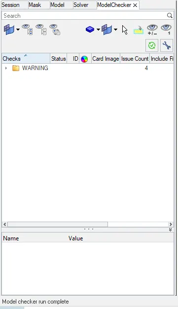
- There is no error as we can see from the above image
Rigid wall creation
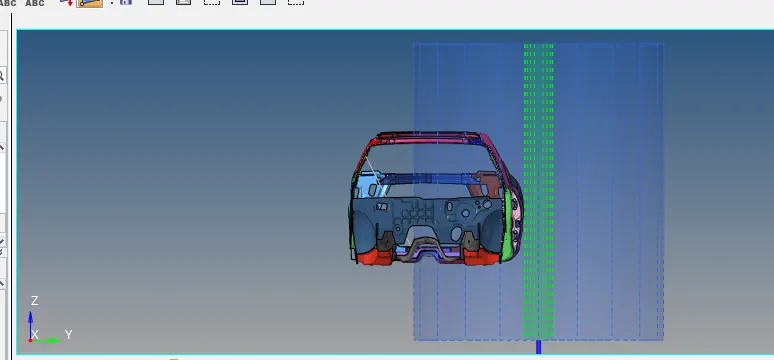
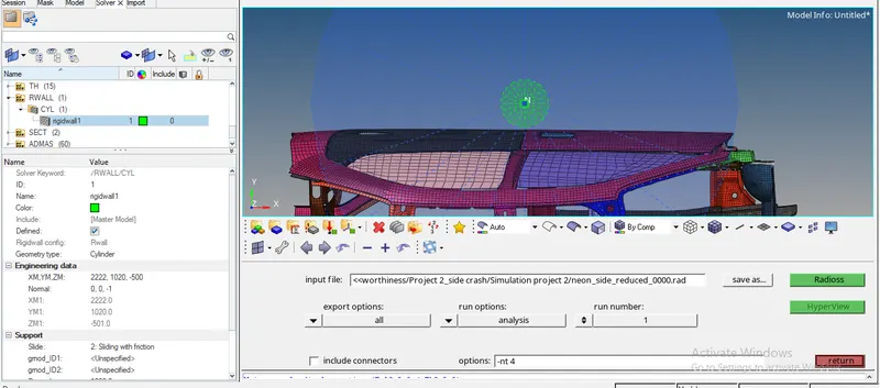
- For the side crash analysis we have to create a rigid wall of cylinder type
- To create the same go to Solver>right click create>Rwall>CYL
- Select the nodes from B pillar, we have to make sure the pole created should cover the whole height of the car
- D search=1000; Cyl Dia=254mm; rigid wall will be created, the cylinder should not be in contact with the car maintain some gap
Create initial velocity card
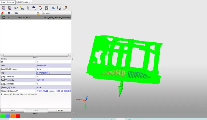
- To create initial velocity open the model in hypercrash
- go to load case>initial velocity>select all the nodes , specify the direction of velocity
- Give the velocity value as 15.6464(Same like frontal crash) in the y direction
Balance the mass and COG
- To see the mass and cog of current model go to mass>balancing
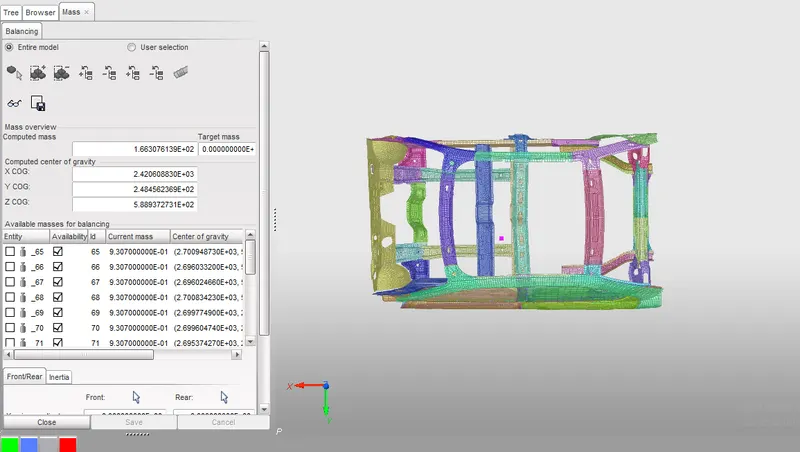
- From the above image we can see the total mass as 166kg,and the cog point is not in required position
- By comparing the model with full car model we have to change the cog point and mass has to bte increased to 700kg
- To add the the mass go to load case>added mass>add the mass wherever required
- Here i am using type 1 mass addition, where the mass added will be equally distributed to all the nodes
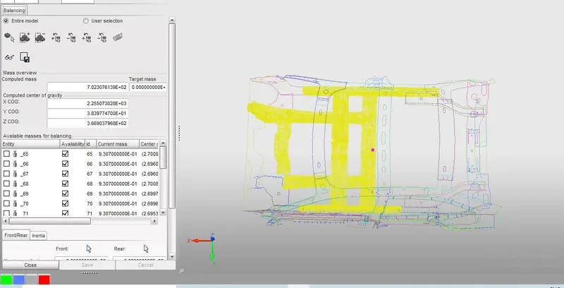
- From the above image we can see the total mass = 700kg and cog is in desired location
- Export the file and open it in hyperworks, from now the steps can be carried out in hyperworks
Mention termination time(Tstop) and Time step
- Go to solver>engine keywords>run>T stop= 80ms
- Go to solver>engine keywords>DT>DT NODA>give T min(minimum time step) value
- Go to solver>Engine keywords>Anim>Anim DT>Give T frequency value, this Tf value will decide your number of frames generated
Output Requests:
Create Sections
- As metion in question we hav to create sections in cross member to obtain the results
- Before creating section we have to create frames for the sections
- To create frames go to solver>right click create>frame >Mov, selct all the N1,N2,N3 nodes
- To create section go to Solver>Right click create>SECT
- In section card, give delta T=0.1; alpha =1.94; Iframe=2;
- Select the frame id of previously created frame, select the same N1,N1,N3 nodes which you have selected to create frame
- gr shell id = selct the elements in the section
- After creating the section card to extract or to plot the results of the section force, we have to create output blocks
- Go to model>output blocks>right click create
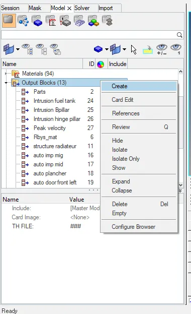
- Create a section card by changing the entity ID into cross section and select the respective cross section card
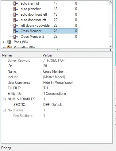
- Do it for both cross member
Create Intrusions
- Create intrusion at mentioned node
- Go to solver>TH>Right click create Node
- Select the node where the intrusions has to be created
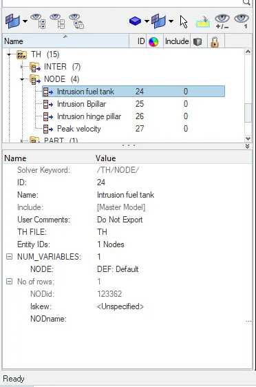
- Same way create a node card for peak velocity at node 337773
- Now all the set up are done we have to run the simulation
- Go to analysis>Radioss>options= -nt 4> save the file in desired location> run the simulation by clicking radioss
RESULTS and Discussion
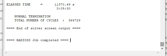
- The total ellapsed time , number of cycles is shown in below image
- Now open the output file from the location you saved the file, we can see the energy error
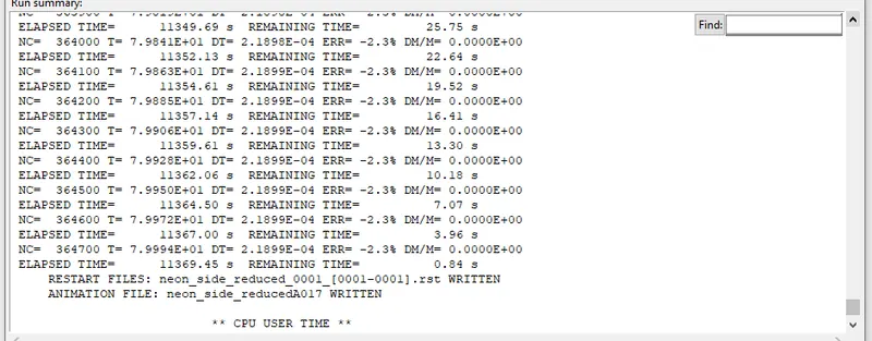
- From the above image we can see the energy error = -2.3%, which is acceptable
- Now we can open .h3d file in hyperview
Displacement=1.465E+03 mm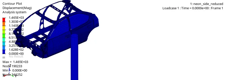
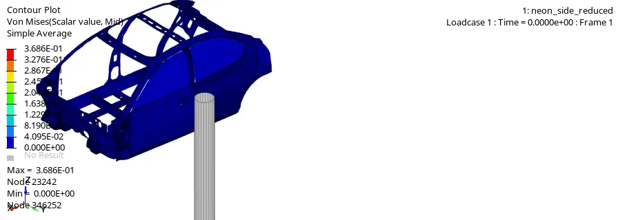
- Von mises=3.686E-01
- Section force of Cross member 1
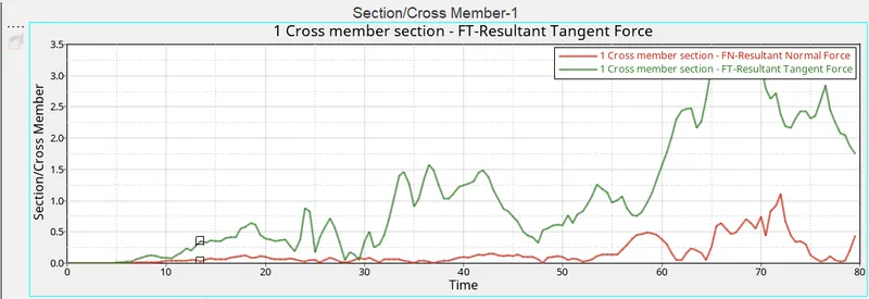
Resultant Normal Force=1.112262
Rsultant Tanget Force=3.279397 - Section force of Cross member 2
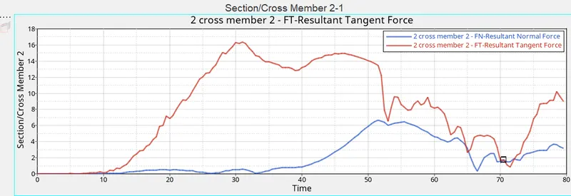
Resultant Normal Force=6.684824
Rsultant Tanget Force=16.377491 - Intrusion Fuel tank
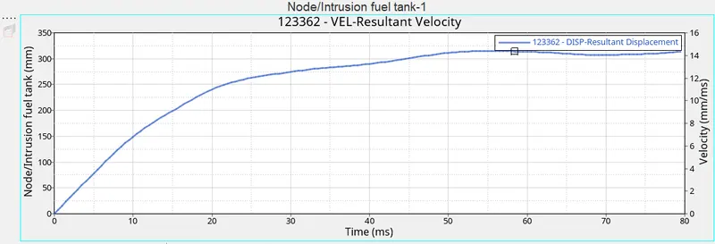
Resultant Displacement=314.571mm - Intrusion B pillar
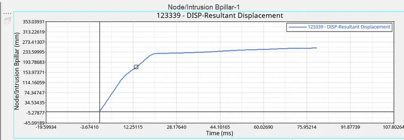
Resultant Displacement=2499.578217mm - Intrusion Hinge pillar
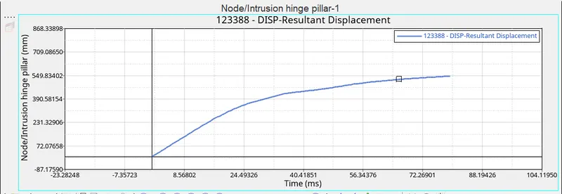
Resultant Displacement=546.63587mm - Peak velocity @ node 33773
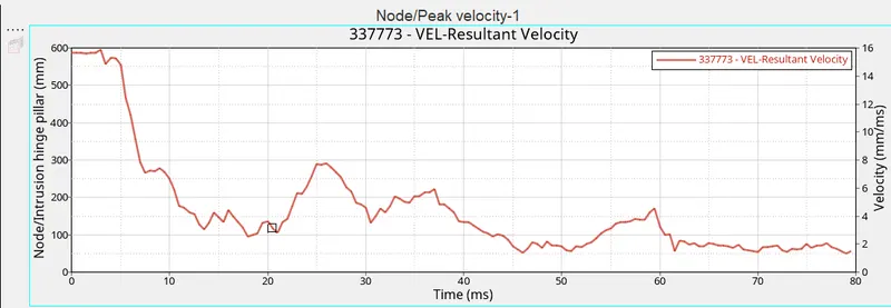
Resultant velocity:
Maximum=15.911763 mm/ms
Minimum=1.299031 mm/ms
Resultant Displacement = 331.384583 mm 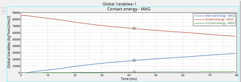
Internal Energy=28958.126953 kg*mm2/ms2
Kinetic Energy
Max=85965.906250 Kg*mm2/ms2
Min=54622.148438 Kg*mm2/ms2
Contact Enenrgy=1820.312256 Kg*mm2/ms2- From the above graph the kinetic energy is decreasing with respect to time
- Internal energy is increasing with respect to time
CONCLUSION:
- The model is set up for side crash with required interface and with no intersections
- Created sections in cross members to get the section force result
- Created Intrusion at required nodes and get the respective results
- Created the output blocks for sections to plot the results in Hypergrpah 2d