Week 1 Challenge
1. 1. Write the steps involved to upload a .std file through web mail?
Answer:-
- Open up with the Staad pro software.
- Explore the option of share from the First window page thats got opened with the software.
- Then the share option will ask for the File name and File location,So browse and select the file you want to Share.
- After Completing the above steps Click on Send mail option and the file will get uploaded through web mail.
1. 2. Name the different materials that can be designed using STAAD Pro.
Answer:-
- Concrete
- Steel
- Wood
- Composite sections
1. 3. Is it possible to capture images in STAAD Pro? If yes how?
Ansrwer:-
Yes it is possible to capture images in Staad pro and it can be done as stated below,
- Go to utilities tab under there is an option for taking picture
- Cliick over that and create your desired shots.
1. 4. Name the three ways by which you can create a model.
The three ways by which a model can be created in staad pro are as follows.
- Analytical Model
- Physical Model
- Building Planner Model
1. 5. Write the steps followed to assign properties in a model.
The steps to assign properties in a model are as follows,
- Go to properties option available in workflow control page tab.
- A window for the properties option will get open.
- Go to define option for defining the property like member sections.
- Then select your shape of the section and define the dimensions of the section.
- Then,use the assignment method available to assign the property into the model.
2. 1. Name any six design parameter involved in RCC design.
The design parameters involved in RCC design may be as follows-
- Modulus of elasticity(E)
- Yield strength of steel(Fy)
- Ultimate tensile strength of steel(Fu)
- Poission's ratio
- Density
- Effective length factors
2. 2. What are the different cursor types available in STAAD Pro?
The different cursor types available in Staad pro are as follows,
- Node cursor
- Geometry cursor
- Beam cursor
- plate cursor
- load cusor
- Solid cursor
2. 3. How will you generate different views for a model? State the steps involved.
To generate the different views for a model thec steps involved are as follows.
- Go to view tab under which search for cubic shaped view objects.
- Seven view cubes are available for the views such as front,back,left,right,isometric,top,bottom.
- Using the above we can generate different views for a model.
2. 4. Explain the procedure to define a “Simply Supported” condition in STAAD Pro
To define a simple support condition in Staad pro the steps involved may be as follows,
- Go to support tab available in workflow control page.
- A dialouge box will open for defining the support conditions.
- Go to create and choose the type of support you want.
- on creating or defining the support condition, it will be available in the dialouge box.
- use the options of assigning them to the model.
2. 5. Name any five topics that you will include while creating DBR.
- Name & location of the project.
- Construction methodology to be used.
- Quality Control(QC)
- Structural layout.
- Method of analysis and codal provisions.
2. 6. Describe the term “Multi material design” of STAAD Pro.
The multi material design of staad pro defines that the Staad pro is capable of handling the model of different material structures like in the Rcc frame structure there may be inclusion of Steel frame structures or any other kind of structure but,Staad pro can take care of them at one shot of analysis which is termed as multi material design in Staad pro.
3. 1. Name the structure systems in STAAD Pro? Explain each system?
The structure system in Staad pro may be as follows,
- Plane Frames- This is the structural system in Staad pro which is suitable for modelling RCC Moment resisting frames.
- Space frames-This is the structural system in Staad pro which is suitable for modelling for truss like structure modelling.
- Trusses-This is the structural system in Staad pro which is suitable for modelling the Truss frames,in either triangullar or rectangular formats for carrying the tension and compression stresses.
3. 2. Explain the coordinate system adopted in STAAD Pro software.
The coordinate system adopted in STAAD Pro software are 3D cooordinate system that is X,Y and Z coordinate system.
3. 3. Elaborate DBR and its uses.
- DBR-Design basis report is the documentation or planning report formation that consists of the design criteria and also considers for the recommendations required to be changed at a later stage,preliminary schedules and cost estimations.
- To specify and compile the data required for analysis and design of the structural elements required.
3. 4. Explain the different types of analysis options in STAAD pro.
- P-Delta analysis
- Pushover analysis
- Buckling analysis
- Linear elastic analysis
3. 5. Explain the difference between Fixed and Fixed But condition.
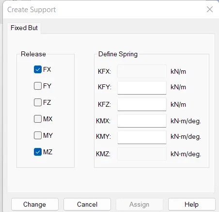
The difference between Fixed and Fixed But condition is that the fixed support is nothing but the kind of support in which all the possible degree of freedom is restrained like all the three degree of translation and all the three degree of rotation is restrained in fixed support condition while in Fixed But condition is a customized support condition available in staad pro that can be customized as per the requirement that is some of the degree of freedom can be realeased in Fixed But condition.
Practical
1. Create a STAAD Model with the following Specification
a. A beam of span 16m
b. Support : Fixed on one end and Roller support(Horizontal) on the other end
c. A point load of 50 kN at the mid-point
d. Draw SFD and BMD using software
Procedure:-
- Open up with the Staad pro software and give a project name and click to create an analytical model.
- To create a beam of 16m two points are required,so specify the first coordinate point as (0,0,0).
- Now, select the point using node cursor then use CTRL+c and CTRL+V automatically it will ask for translational distance so give x=16m as prescribed in the given data.
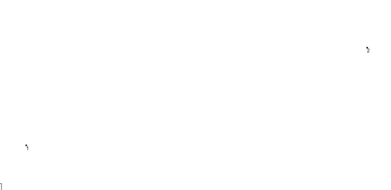
- After creating the points we are required to define the properties of the beam, so Go to properties and define a rectangular beam of your desired dimensions.
- Use the option assign to view to assign the beam property in the model from the properties tab.
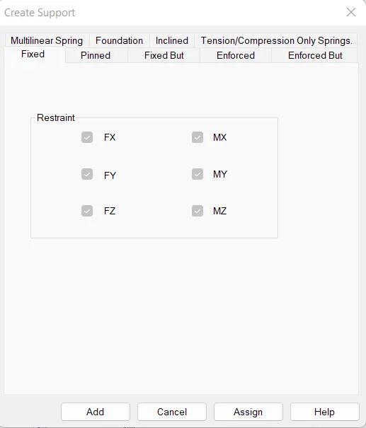
- Now, create fixed support and roller support to assign the supports at each end.
- Create fixed support,
- Create roller support,
- Model after providing the support conditions,
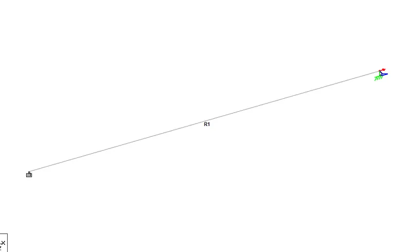
- Defining a point load of 50 kn to apply at the mid point of the beam are as follows,
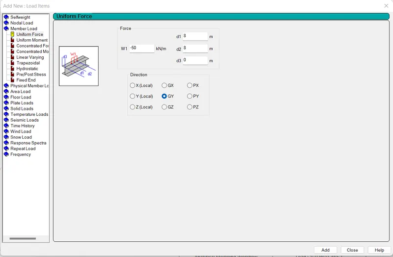
- Appying the member load to the model.
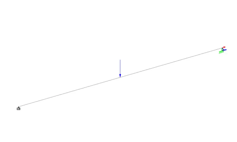
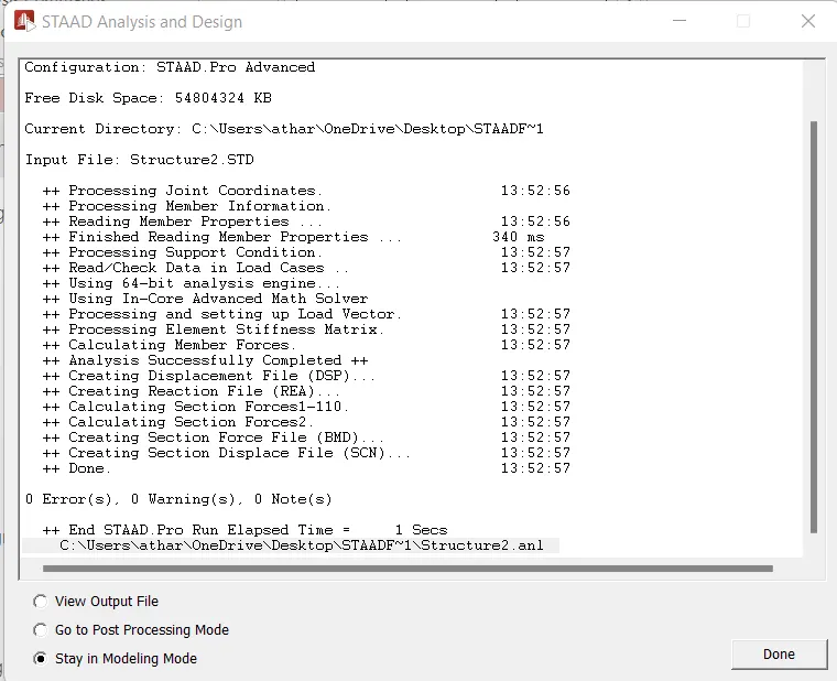
- Now, as the model is ready we can proceed to perform analysis,To do so
- First go to analysis option from project control flow page,
- Go to define commands to add to perform analysis.
- Once it is done,press on run analysis
Results:-
- Draw SFD from software are as follows,
Go to postprocessing mode and click on beam results,then select Fy for the shear force drawing.
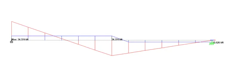
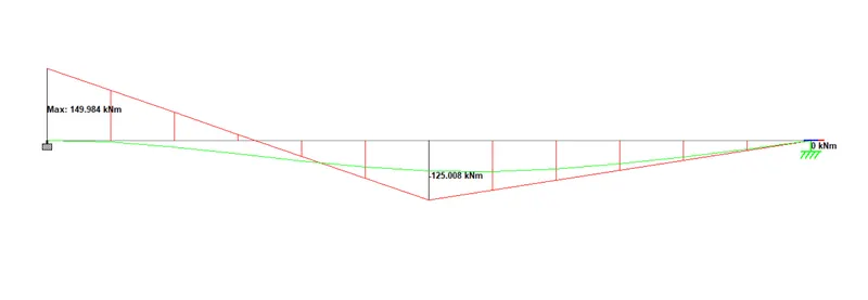
- Select Mz for bending moment diagram,
- As we can see from the results bending moment value at one end is zero due to the fact that it is a roller support and in the roller support we release the Mz bending moment.