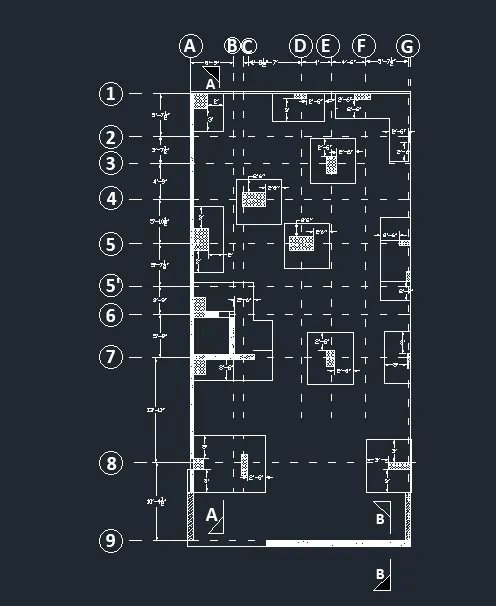
Creating a Wardrobe detailed drawing, Floor Plan, Kitchen Layout and Column Detail using AutoCad
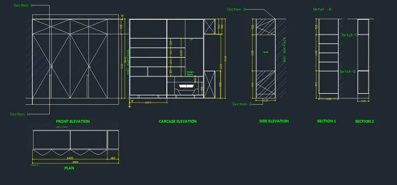
1. Draw the elevation and details of a wardrobe as shown in the Figure below. After sketching, you need to provide the dimensions and text with the use of layers. Use proper text styles and dimension methods to document it. Also, assume dimensions, wherever needed.
Note: All dimensions are in mm.
Aim:- To draw the elevation and details of the wardrobe as given in the figure.
Procedure:-
- Start with the autocad⮕setup the units⮕Analyse how much the size of the screen is required ⮕set the screen size using limmax⮕now the screen is ready for the drawing.
- The elevation of the wardrobe is drawn using the commands like line tool,offset,trim,extend,hatching etc.
- texts and dimensions are provided for refrence for specific objects.
- texts and dimensions are categorised into differen layer with different colours as well.
- The missing dimensions are suitably assumed here and drawn as given in the figure.
Result:- The resultant figure from the auto cad is as follows,
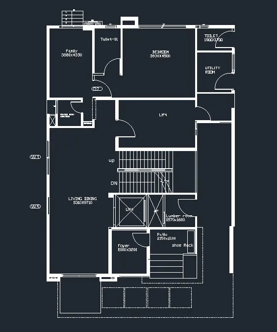
Q2. Draw the floor plan as shown in the Figure. Use the proper drafting tools to sketch the plan. Do not hatch or draw the furniture. You need to draw the floor plan with the following:
Note: You can also import the Floor_Plan.pdf into your current drawing and start working on the project. You need to scale the imported pdf file using reference option. All dimensions are in mm.
- Walls (Exterior and Interior)
Wall Thickness: Exterior Wall- 230mm, Interior Wall: 150 mm (Wherever Required)
- Doors and Windows: Assume the size of the doors and window.
2.1 Stairs: Tread-300mm, Riser-150mm
- Insert Text wherever required
- Insert the dimensions using proper dimension techniques
Aim:- To draw the floor plan as given in the figure.
Procedure:-
- Start with the autocad⮕setup the units⮕Analyse how much the size of the screen is required ⮕set the screen size using limmax⮕now the screen is ready for the drawing.
- The floor plan can be drawn drawn using the commands like line tool,offset,trim,extend,hatching etc.
- texts and dimensions are provided for refrence for specific objects.
- The furniture and other are not drawn here as directed in the question.
- The missing dimensions are suitably assumed here and drawn as given in the figure.
Result:- The resultant figure from the auto cad is as follows,
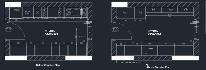
Q3. Create the Kitchen Layout as shown in the Figure below. Also, use proper dimension techniques to dimension the kitchen layout. Also, insert text wherever required. All dimensions are in mm.
Aim:- To draw the kitchen layout as given in the figure.
Procedure:-
- Start with the autocad⮕setup the units⮕Analyse how much the size of the screen is required ⮕set the screen size using limmax⮕now the screen is ready for the drawing.
- The kitchen layout can be drawn using the commands like line tool,offset,trim,extend,hatching etc.
- texts and dimensions are provided for refrence for specific objects.
- The furniture and other are drawn here as directed in the question.
- The missing dimensions are suitably assumed here and drawn as given in the figure.
Result:- The resultant figure from the auto cad is as follows,
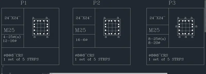
Q4. Sketch the column details as shown in Figure. Insert dimensions and text in the figure. Refer to the bar sizes from the schedule.
8mm ---- 0.31 Inches
25mm--- 1 inches
16mm—0.62 inches
Aim:- To draw the column details as given in the figure.
Procedure:-
- Start with the autocad⮕setup the units⮕Analyse how much the size of the screen is required ⮕set the screen size using limmax⮕now the screen is ready for the drawing.
- The column dtails drawing can be drawn drawn using the commands like line tool,offset,trim,extend,hatching, circle etc.
- The bar drawn is a circle which is hatched using solid hatch.
- texts and dimensions are provided for refrence for specific objects.
- The sizes of the bars are drawn here as directed in the question.
- The missing dimensions are suitably assumed here and drawn as given in the figure.
Result:- The resultant figure from the auto cad is as follows,
Q 5. Draw the Raft Layout as shown in the Figure. Assume the column size as per your knowledge. You can take the sizes as: 24”x24”, 9” x 24”, 9” x 18”, and 9’ x 24”. You can import the raft_foundation.pdf to ensure the missing dimensions.
Aim:- To draw the raft foundation layout details as given in the figure.
Procedure:-
- Start with the autocad⮕setup the units⮕Analyse how much the size of the screen is required ⮕set the screen size using limmax⮕now the screen is ready for the drawing.
- The raft layout can be drawn drawn using the commands like line tool,offset,trim,extend,hatching etc.
- using the grid numbers like roman numerals and alphabets,the intersection of the two acts as the centre for the column,with that reference the footing of the layout is drawn.
- texts and dimensions are provided for refrence for specific objects.
- The sizes of the columns are assumed suitably as directed in the question.
- The missing dimensions are suitably assumed here and drawn as given in the figure.
Result:- The resultant figure from the auto cad is as follows,