Reinforcement Detailing of Beams from ETABS output
Challenge 7 – Detailed design of concrete buildings -1
Detail design of beams in Etabs 2018.
The ETABS file for a G+4 building is provided. Run the analysis and design the RCC Moment ResistingFrame. The following challenge deals specifically with two continuous beams in the 1st floor.
1) 3 span continuous beam along grid A
2) 7 span continuous beam along grid 3
Address the following issues thereafter.
• Provide details of longitudinal and shear reinforcement for the two continuous beams. Sketch the beam elevation details or draft it using autocad software. A sample of how beam elevation details is prepared in consultancy firms is provided below. Participants can prepare it as per their preference:
Aim:- To design and detailing of the Beam for the given Moment Resisting Frame,The detailing has to be done for the given beams one along grid A 3 span continuous beam and other along grid 3 for 7 span continuous beam.
Procedure:-
- Download the Etabs model file and open it up using the sotware.
- Perform Analysis of the model.
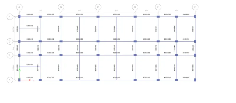
- Perform the analysis of the model by pressing the F5 key or by pressing the play button available in the tool palletes,wait for the analysis to get completed till the deflected shpe of the model appears.
- View the deflected model in 3D.
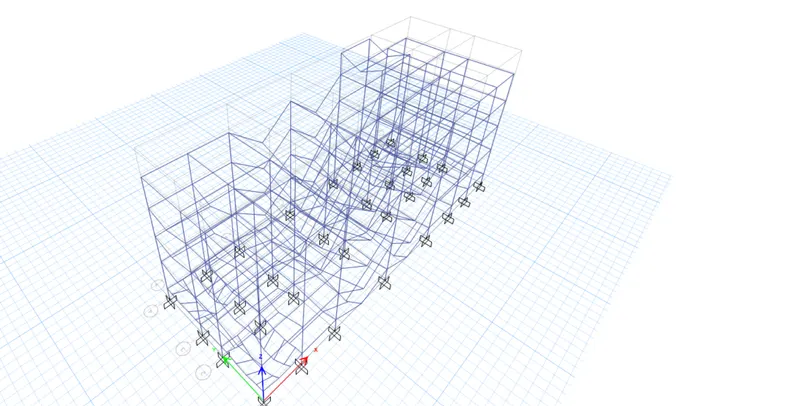
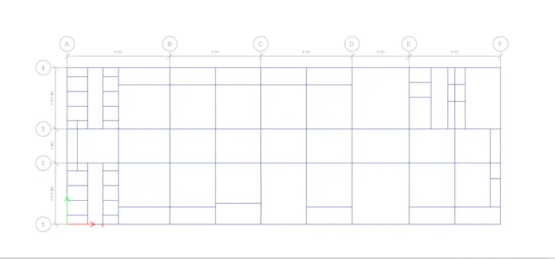
- Perform the concrete frame design for the model.
- Before running the concrete frame design for the model,it is mandatory to check that the proper design codes are selected for the frame design or not.
- To do so,Click on the dropdown of the frame design option under which choose view/revise preferences and in the opened dialouge box check for your requirements.
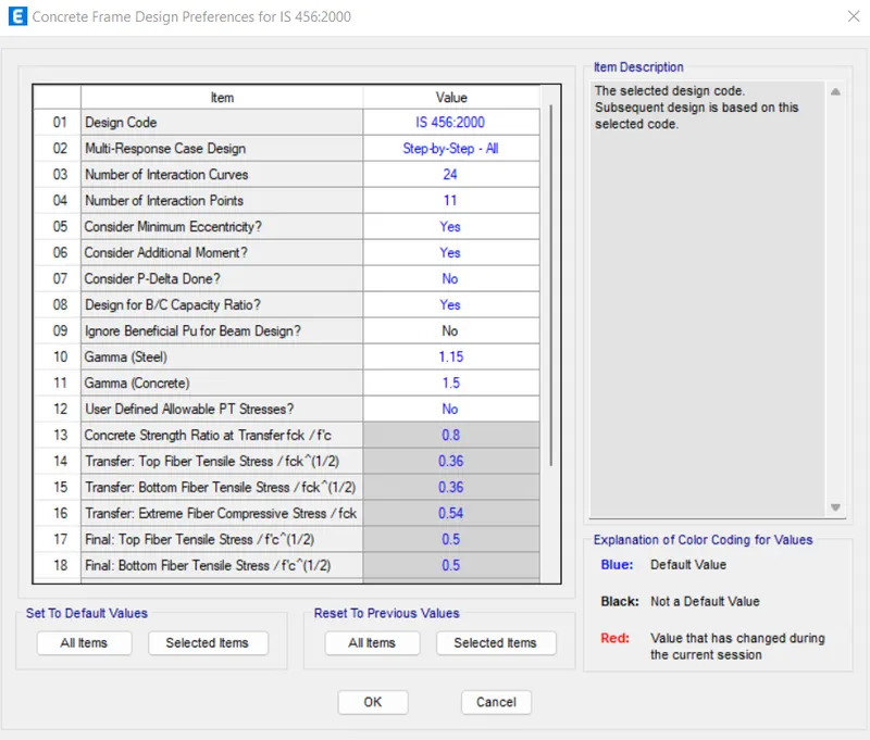
- Once everything is found to be okay,we can go ahead to perform concrete frame design.
- just click over the logo concrete frame deign and it will start the designing process.
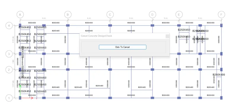
- Once the concrete frame design is processed following view of the model can be seen in the model space.
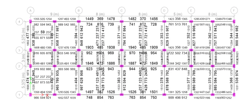
- From many different kinds of result values we are required to have the Area of reinforcement for the beams.
- Following are the snaps of the Grid A and Grid 3 beam longitudnal reinforcement values.
1) 3 span continuous beam along grid A
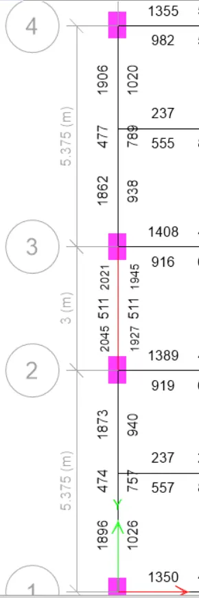

- Using the above reinforcement area results we have to design and detail the continuous beams.
1.Design of the 3 span continuous beam along grid A
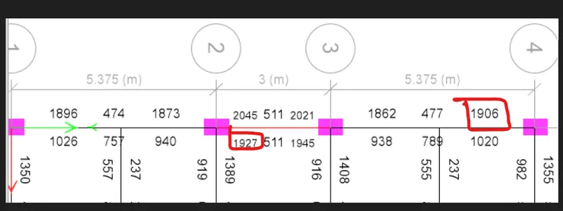
- As we know that Reinforcement has to be designed for the maximum Ast.
- The maximum value of Ast in the 3 span continuous beam of Grid can be extracted as
Ast top=1906 mm2
Ast bottom R/f=1927 mm2
- Now, we have to adjust the reinforcement area with the available reinforcement diameter of bars in the market.
- For top R/f Ast=1906 mm2 let us provide 2-T32 bars and 1-T20 bars which sums up the total area of 1921 mm2,since it is more than the rerquired, so it dsatisfies the requirement ,hence ok.
- For bottom R/f Ast=1927 mm2
- let us provide 2T-32 and 1T-25 which sums up the total area of 2098 mm2,since the provided area of reinforcement is higher than the required so it satisfies the requirement hence,ok.
- While providing the reinforcement on the top,it is a good practice to cut the reinforcement in the middle portion but,at the bottom the reinforcement will start from one end and will end at the other end.
- For detailing the rebar in the auto cad development and anchorage lengthis required,
- Calculation of the anchorage length for the top reinforcements.
Formulae for the anchorage length as per IS 13920
Anchorage length=Ld+10db, Where Ld is development length and db is nothing but the diameter of the bar for which we are calculating the anchorage length.
Ld can be calculated as, Ld = φ σst/4τ bd
In the model,section properties arte provided are concrete of M30 grade while steel rebar for longitudnal reinforcement of HYSD415 are provided.
τ bd value from the IS 456:2000 ,we know=2.72
so,Ld for T-32 rebar,
Ld=((32x415)/(4x2.72))
Ld=1221 mm ,but as per IS 13290 add 10db in the development length so,
anchorage length=1221+320=1541 mm.
similarly Ld for T25 rebar = 954mm, anchorage length=954+250=1204 mm.
Now,calculations for providing the shear R/f
considering the depth of column as 600mm,
As per IS 13290,from the end support upto 2d of the beam confined shear reinforcement shall be provided.
=2d, d=600-25-32=543 mm,2d=2x543=1086 mm
The area of shear R/f from the etabs at the support is equal to 1481 mm2.
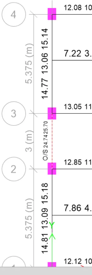
let's provide 2L-T8 for the shear R/f.
one round of 2L-T8 counts for 100 mm2,so,for 1481 mm2
Total numbers required are=1481/100=14.81, let's take=15 No.s
For spacing we have
Spacing=(1086/15)=72.4 mm, let's consider 75 mm c/c
- So,for the Shear reinforcement we are arrived to provide 2L-T8@75mm C/C. upto 2d from the left support at Grid A of span 1 from left support.
- As per Is 13290 spacing should be ≤d/4,8db or 100mm,whichever is lesser.
- so,75mm ≤d/4=543/4,8x32,100mm
- Here in our case it satisfies the codal provisions.
- Now,the shear R/f in the middle support,
- Ast=1309 mm2
let's provide 2L-T8 for the shear R/f.
one round of 2L-T8 counts for 100 mm2,so,for 1309 mm2
Total numbers required are=1309/100=13.09, let's take=13 No.s
For spacing we have
Spacing=(2604/13)=200 mm, let's consider 180 mm c/c.
As per Is 13290 spacing should be ≤d/2.
- so,190mm ≤d/2=543/2=271mm
- Here in our case it satisfies the codal provisions.
- The detailing of the reinforcement in the Auto cad Software is as follows,
- Span 1 of Grid A,
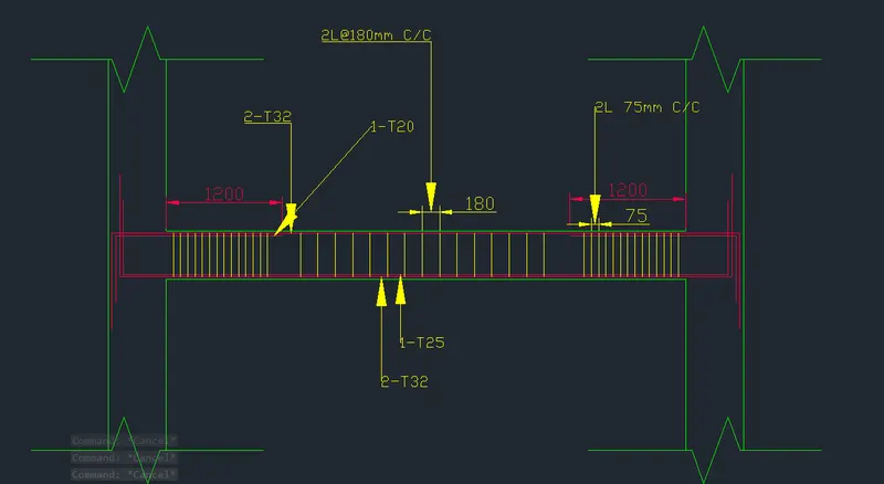
Similarly calculated the reinforcement details of the Span 3 of grid A and the reinforcement details are drawn in the autocad software as follows,
- Span 3
- Span 2.
Span 2 of Grid A is failed in the design process and the reason listed by the etabs software for the failure is

- The possible reasons for the failure of the middle span along grid A are as follows.
- Due to the overstressing of shear near the right support,the shear stress provided by the analytical model exceeds the corresponding limiting value as stated by the design codes.
- Also, the scetion of the member provided causes the failure.
- The Possible ways by the virtue of which its design failure can be rectified are as follows.
- The major cause is the overstressing so, if the stressing is reduced somehow the problem can be rectified and it can be done in two following ways.
- As we know shear is nothing but load/area so,
- if we increase the cross-sectional area correspondingly,the stress will get decreased.
- or decrease the load value so that the overstressing can be reduced.
- Similarly calculating the reinforcement details of Grid 3 Beam.
2) 7 span continuous beam along grid 3

- Using the above reinforcement area results we have to design and detail the continuous beams.
1.Design of the 7 span continuous beam along grid 3
- As we know that Reinforcement has to be designed for the maximum Ast.
- The maximum value of Ast in the 3 span continuous beam of Grid can be extracted as
Ast top=1940 mm2
Ast bottom R/f=1501 mm2
- Now, we have to adjust the reinforcement area with the available reinforcement diameter of bars in the market.
- For top R/f Ast=1940 mm2 let us provide 2-T32 bars and 1-T25 bars which sums up the total area of 2097 mm2,since it is more than the rerquired, so it satisfies the requirement ,hence ok.
- For bottom R/f Ast=1501 mm2
- let us provide 3T-25 and 1T-12 which sums up the total area of 1586 mm2,since the provided area of reinforcement is higher than the required so it satisfies the requirement hence,ok.
- While providing the reinforcement on the top,it is a good practice to cut the reinforcement in the middle portion but,at the bottom the reinforcement will start from one end and will end at the other end.
- For detailing the rebar in the auto cad development and anchorage lengthis required,
- Calculation of the anchorage length for the top reinforcements.
Formulae for the anchorage length as per IS 13920
Anchorage length=Ld+10db, Where Ld is development length and db is nothing but the diameter of the bar for which we are calculating the anchorage length.
Ld can be calculated as, Ld = φ σst/4τ bd
In the model,section properties arte provided are concrete of M30 grade while steel rebar for longitudnal reinforcement of HYSD415 are provided.
τ bd value from the IS 456:2000 ,we know=2.72
so,Ld for T-32 rebar,
Ld=((32x415)/(4x2.72))
Ld=1221 mm ,but as per IS 13290 add 10db in the development length so,
anchorage length=1221+320=1541 mm.
similarly Ld for T25 rebar = 954mm, anchorage length=954+250=1204 mm.
similarly Ld for T12 rebar = 458mm, anchorage length=458+120=578 mm.
Now,calculations for providing the shear R/f
considering the depth of column as 500mm,
As per IS 13290,from the end support upto 2d of the beam confined shear reinforcement shall be provided.
=2d, d=500-25-32= 443mm,2d=2x443=886 mm
The area of shear R/f from the etabs at the support is equal to 1433 mm2.

let's provide 2L-T8 for the shear R/f.
one round of 2L-T8 counts for 100 mm2,so,for 1481 mm2
Total numbers required are=1433/100=14.33, let's take=15 No.s
For spacing we have
Spacing=(886/15)=59.06 mm, let's consider 70 mm c/c
- So,for the Shear reinforcement we are arrived to provide 2L-T8@75mm C/C. upto 2d from the left support at Grid 3 of span 1 from left support.
- As per Is 13290 spacing should be ≤d/4,8db or 100mm,whichever is lesser.
- so,75mm ≤d/4=543/4,8x32,100mm
- Here in our case it satisfies the codal provisions.
- Now,the shear R/f in the middle support,
- Ast=2200 mm2
let's provide 2L-T8 for the shear R/f.
one round of 2L-T8 counts for 100 mm2,so,for 2200 mm2
Total numbers required are=2200/100=22,
For spacing we have
Spacing=(2228/22)=100 mm, let's consider 110 mm c/c.
As per Is 13290 spacing should be ≤d/2.
- so,110mm ≤d/2=443/2=222 mm
- Here in our case it satisfies the codal provisions.
- The detailing of the reinforcement in the Auto cad Software is as follows,
- Span 1 of Grid 3,
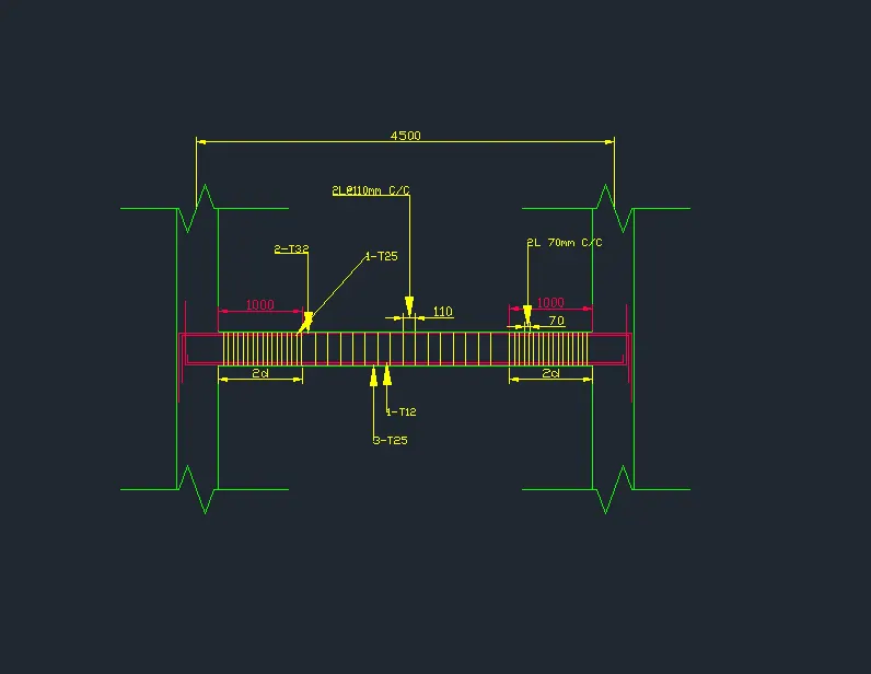
- Span 2
- Span 3
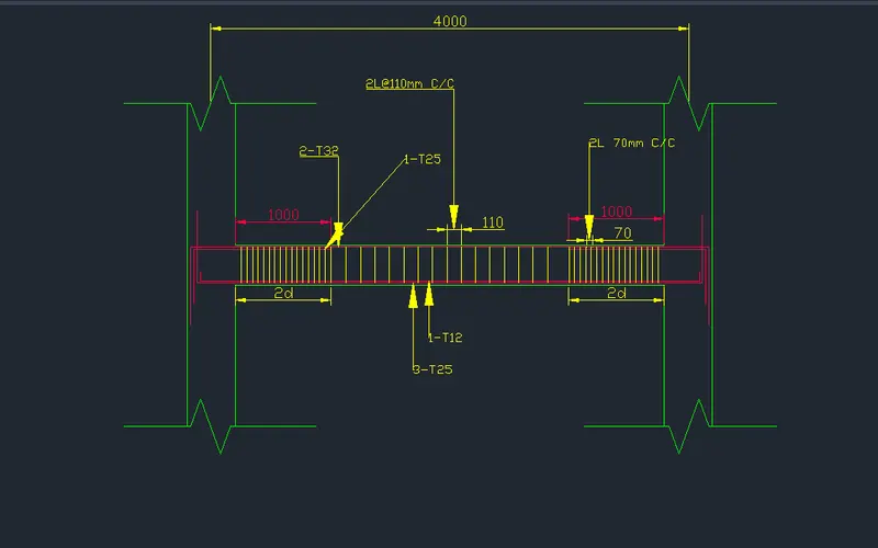
- Span 4
- Span 5
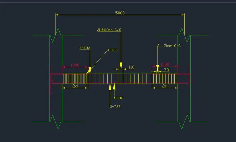
- Span 6
- Span 7
- Calculate value of the maximum shear force in any one of the spans in both the continuous beams, as per clause 6.3.3 (b) in IS 13920 – 2016. Also, confirm these values from shear force demand calculated by ETABS.Please note that if longitudinal reinforcement provided is more than required (as per ETABS results), the shear force demand will vary from what is provided by ETABS.
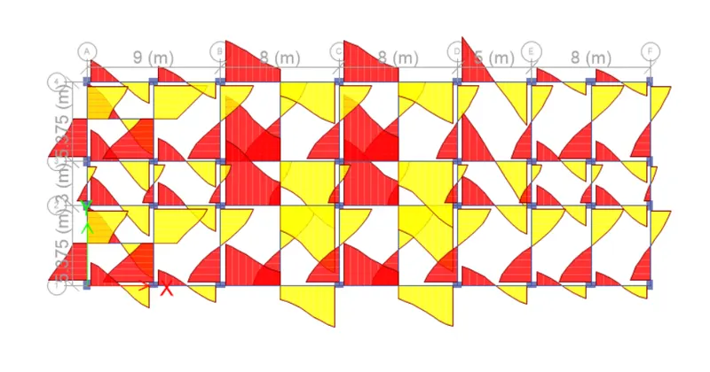
There are mainly two ways of sway shear is possible one on the right side and the other on the left side.
As per IS 13290 clause 6.3.3 suggests that the area of reinforcement provided in the shear shall be able to take care of the sway shear induced on either side of the sway possible.
The code has suggested formulae also for calculating the sway shear on either side.
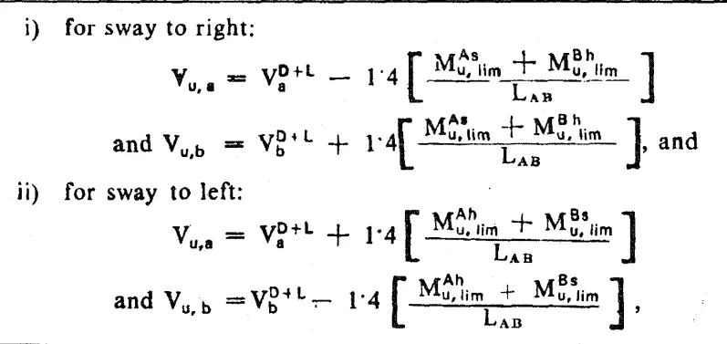
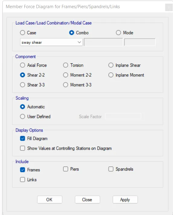
To get the load combination values for the above formulae a ne load combination has to be introduced in the model as
1.2(DL+LL+brickwall+floor fineshes)
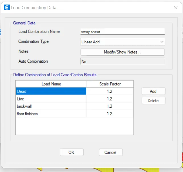
- Now, to extract the results,we have
Sway to the Right
- Vua = 46 KN
- Vub = 223 KN
Sway to the Left
- Vua = 185 KN
- Vub = 45 KN
so,the maximum shear arrived can be seen as 223kN,so this value Should be imparted by the provided shear reinforcements for the safe and sound design.
- Calculating the Shear force that can be taken by the design shear reinforcements.
Vus = 0.87fy Asv d / Sv
= 0.87x500x110x570 / 75
Vus = 330 KN
so, Vus = 330 KN>223KN, We can conclude now that the design shear reinforcement is safe against sway on either side.