Creating various 3D Models like Furniture, Footing, Girder, Column drop with panel and Gable Wall in AutoCad
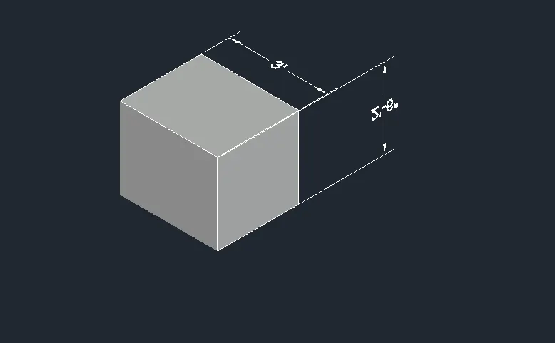
1. Create a 3D Furniture element as shown in the Figure. Assume dimensions which are missing.
Aim:- To Create a 3D Furniture element as shown in the Figure:-
Introduction:-Creating a 3D model, the progression is in such a way that
- wireframe models- creating wireframe models using lines.
- Surface-Surfaces are created from the enclosed wireframes.
- solid- Solids are created from surfaces.
Procedure:-
- Start with the autocad⮕ set the unit type as decimal with the precision 0 and the insertion unit as milimeters⮕analyse the screen required for the drawing and set the screen size using limmax⮕Zoom⮕ all⮕ now the screen is ready for the drawing.
- Switch the workspace to 3D basics and keep the screen in top view.
- Create a box ⮕with giving cube length=3',width=2'6'',height=2'6'',
- Type command UCS ⮕F⮕select the face for dimensioning⮕provide the required dimensions.
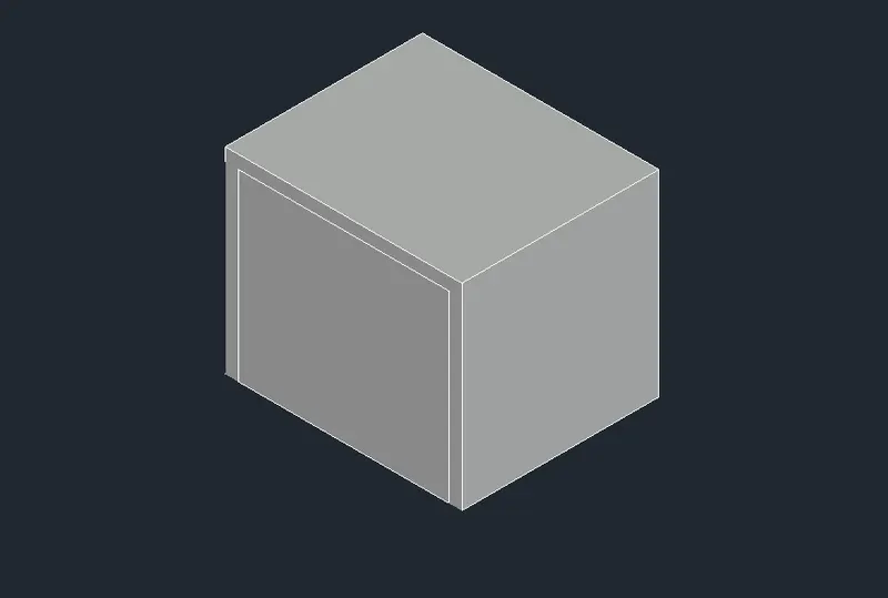
- using the front face draw a line above the edge and take off set of 2'' in the same face.⮕do this on the the the front edges.
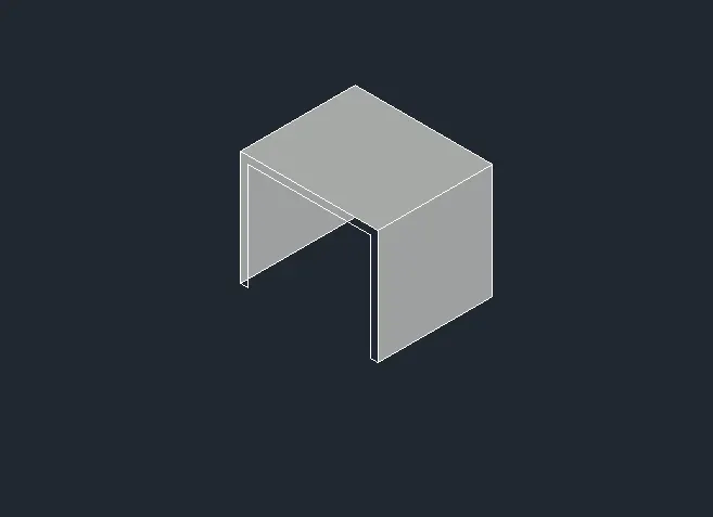
- creating the face to scrude⮕scrude the rectangle formed on front face in its negative direction that is inside of the the furniture for 2'6''⮕i.e. upto the back face.
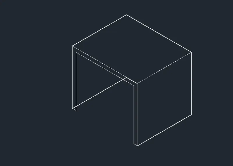
- view the model in hidden mode and match with the given fig.
- create surfaces on the rectangular sections.
- using line command draw lines on the edge of the sections to use the command "edgesurf" to create surfaces.
- view the model in shaded.⮕using snipping tool take snaps after each steps.
Results:- The snaps of the model created are as follows.
2. Create the 3d Model of an Isolated footing as shown in Figure.
Aim:- To Create a 3D model of an isolated footing as shown in the Figure:-
Introduction:-Creating a 3D model, the progression is in such a way that
- wireframe models- creating wireframe models using lines.
- Surface-Surfaces are created from the enclosed wireframes.
- solid- Solids are created from surfaces.
Procedure:-
- Start with the autocad⮕ set the unit type as decimal with the precision 0 and the insertion unit as milimeters⮕analyse the screen required for the drawing and set the screen size using limmax⮕Zoom⮕ all⮕ now the screen is ready for the drawing.
- Switch the workspace to 3D basics and keep the screen in top view.
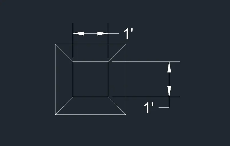
- create a rectangle of @2',2'
- offset the rectangle for 6'' to create a rectangle of 1' x 1'
- select the smaller rectangle and move the rectangle as @0,0,2'6''
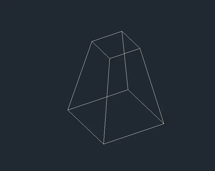
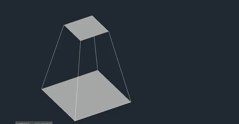
- join the corners of smaller rectangle to larger rectangle and create faces at top,bottom,and all the four side faces.
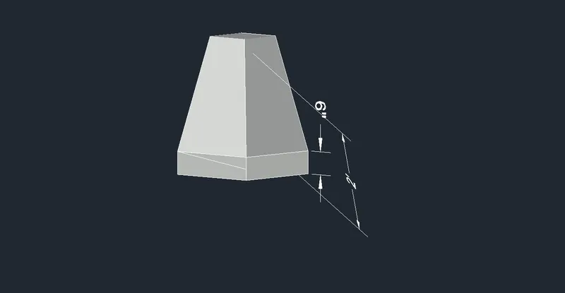
- select the front face and draw a line 6'' downwards ⮕do the same for all the four corners⮕as the face is created this way⮕create faces using "3DFACE" for all the faces.
- view the model in shaded and hidden mode.⮕using snipping tool take snaps after each steps.
Results:- The snaps of the model created are as follows.
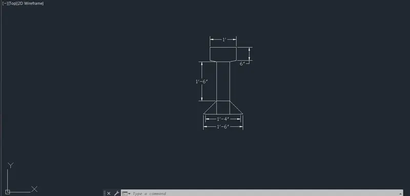
3. Create the 3D view of the AASTHO Type Girder.
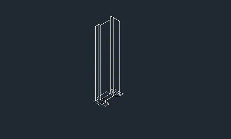
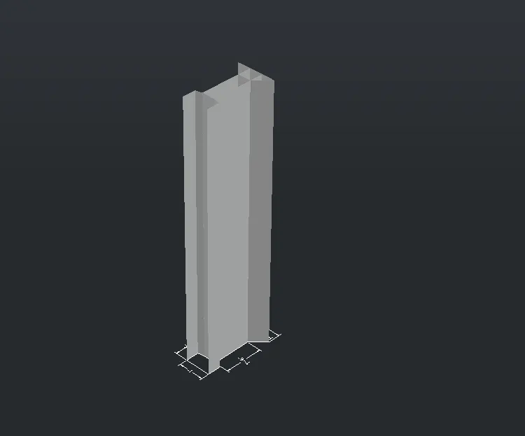
Aim:- To Create the 3D view of AASTHO type girder as shown in the Figure:-
Introduction:-
AASTHO Girder-This is a kind of bridge girder which is introduced by the American Association of State Highways and Transportation officials.
Creating a 3D model, the progression is in such a way that
- wireframe models- creating wireframe models using lines.
- Surface-Surfaces are created from the enclosed wireframes.
- solid- Solids are created from surfaces.
Procedure:-
- Start with the autocad⮕ set the unit type as decimal with the precision 0 and the insertion unit as milimeters⮕analyse the screen required for the drawing and set the screen size using limmax⮕Zoom⮕ all⮕ now the screen is ready for the drawing.
- Switch the workspace to 3D basics and keep the screen in top view.
- create the edge face geometry of the girder using line tool⮕ mark the required dimensions.
- Turn the view in 3D using 3Dview cube.
- select extrude and select the drawn geometry as object.
- excrude the geometry for 10' in z direction.
Results:- The snaps of the model created are as follows.
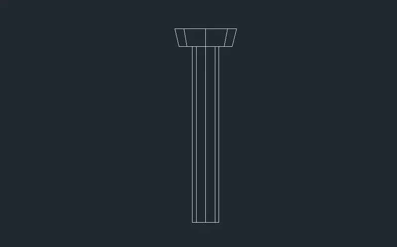
4. Create a 3d Model of a drop column with panel as shown in section and isometric view.
Aim:- To Create a 3D model of a drop column with panel as shown in the Figure:-
Introduction:-Creating a 3D model, the progression is in such a way that
- wireframe models- creating wireframe models using lines.
- Surface-Surfaces are created from the enclosed wireframes.
- solid- Solids are created from surfaces.
Procedure:-
- Start with the autocad⮕ set the unit type as decimal with the precision 0 and the insertion unit as milimeters⮕analyse the screen required for the drawing and set the screen size using limmax⮕Zoom⮕ all⮕ now the screen is ready for the drawing.
- Switch the workspace to 3D basics and keep the screen in top view.
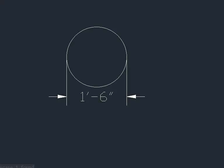
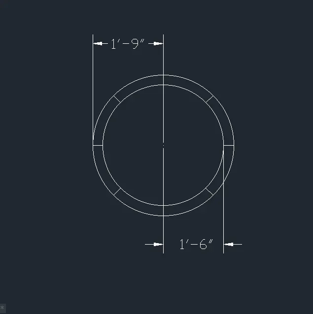
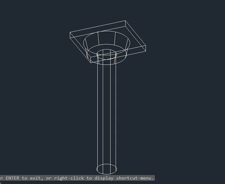
- creating the circle for a dimeter of 1'6'' in the top view.
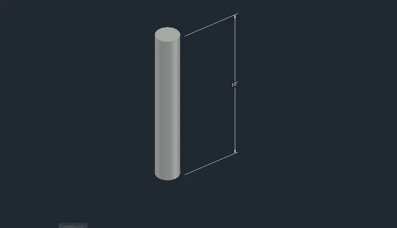
- Excrude the circle to create column for 10' height.
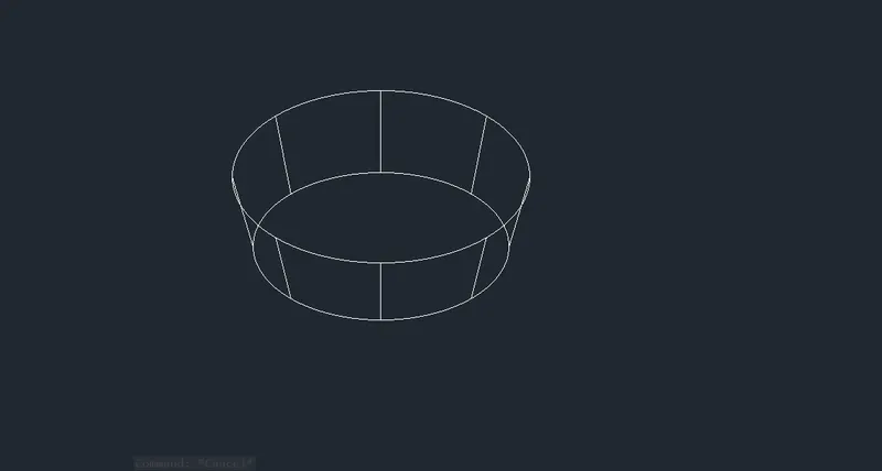
- Creating a cone of base dia as 1'6'' and the top radius as 21'',provide the height of the cone as 1'.
- Select the cone created and overlap the cone on the circle by using move command,take care to coincide the geometrical centre of the cone to the circle ⮕ Do this all in Top view.
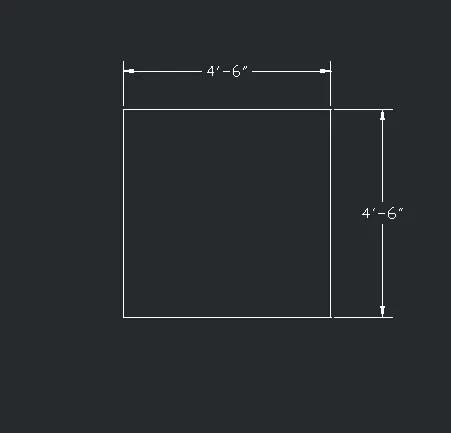
- Now create a rectangle as @4'6,4'6⮕ overlap the created rectangle similarly as in the above step.
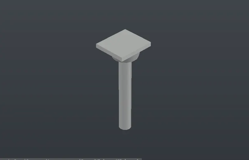
- See th model in 3D if the model is matching as in the fig ⮕ take snap of the model in different modes.
Results:- The snaps of the model created are as follows.
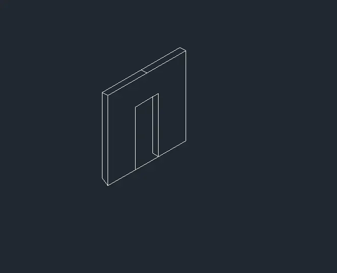
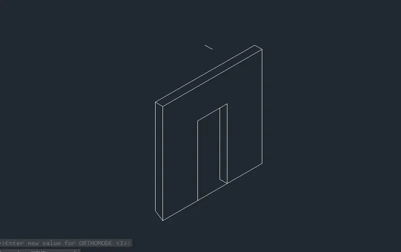
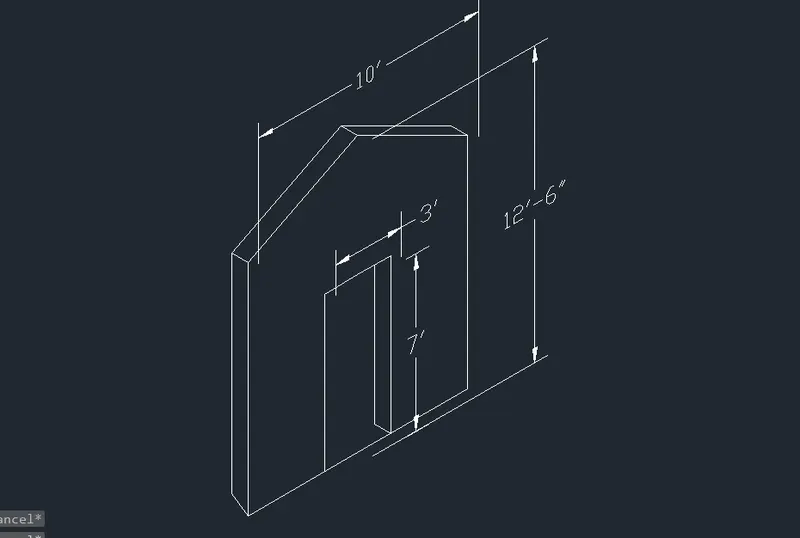
5. Create the 3d model of a wall as shown in Figure. Consider wall thickness as 9”.
Aim:- To Create a 3D model of a wall as shown in the Figure:-
Introduction:-Creating a 3D model, the progression is in such a way that
- wireframe models- creating wireframe models using lines.
- Surface-Surfaces are created from the enclosed wireframes.
- solid- Solids are created from surfaces.
Procedure:-
- Start with the autocad⮕ set the unit type as decimal with the precision 0 and the insertion unit as milimeters⮕analyse the screen required for the drawing and set the screen size using limmax⮕Zoom⮕ all⮕ now the screen is ready for the drawing.
- Switch the workspace to 3D basics and keep the screen in top view.
- Using the line command creating the wall frame with the help of rectangular coordinate system.
- Create a door of 3' x 7' as given in the figure.
- Assuming the width of the wall as 9'' as directed in the question.
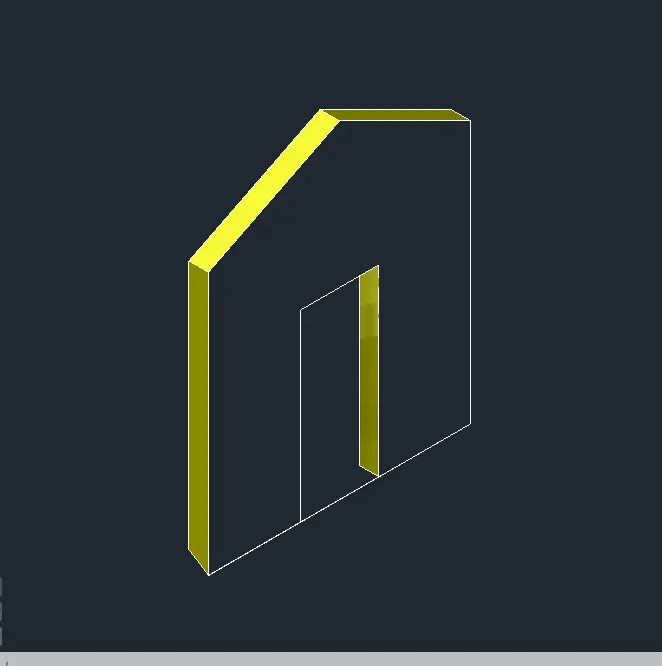
- create surface on 3D faces and provide with a color to make it more visual.
Results:- The snaps of the model created are as follows.