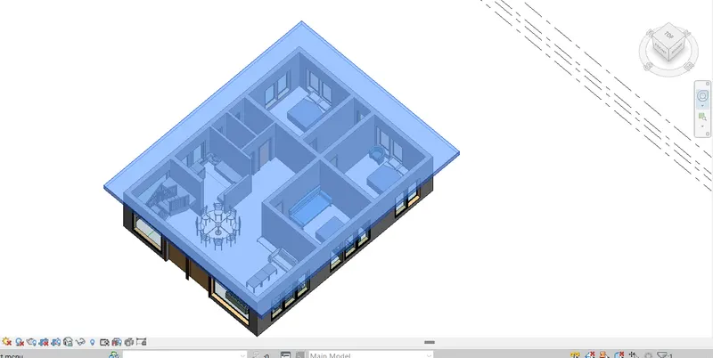
Creating Levels, Grids, Layout and model elements for a residential unit using REVIT
1) What is BIM? Summarize the features of BIM and benefits of using BIM over 2D CAD tools.
BIM stands for building information modelliling which is basically a methodology by which multidisciplinary datas are collected from the created model in the software like revit to optimize its suitability,feasibility,sustainability and other standards required for the evaluation purposes. BIM gathers every single piece of information which are given to the model during its course of modelling,It also gathers information like cost estimation,multilevel drawings,sections etc through the created building model in the software like revit.
The features of BIM and benifits of using BIM over 2D CAD tools.
- Herein BIM,the main focus is on to create a suitable model of the building as different drawings which are required during the phase of construction can be generated from the created 3D model itself while in CAD our focus is on to develop the planning layout,section drawings etc.
- BIM helps to gather other multidisciplinary information as a visual representation which helps in communicating and understanding of the project in a better way while auto cad doesn't have such feautres.
- BIM Establish collaboration between the team members even after different teams working in different locations and on different disciplines.
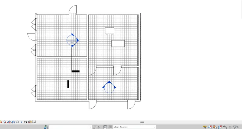
2) Understand the concept of Categories, Families, Elements, Instances in Revit. Go to Insert Tab, choose a category. Pick a family and element. Understand the instances and insert it to Revit model.
Aim:- To develop the understanding of the concept of Categories, Families, Elements, Instances in Revit and picking and inserting the family element in the revit model.
Introduction:-
- Categories- Basically there are two categories defined in the revit one is model categories and other is annotation categories. The model category comprises of the build elements such as wall,roof,door,window,column etc while annotation categories marks the elements such as dimensioning,texts,tags etc.
- Families- Families are like the blocks in revit under which different preloaded elements are available which can be used in our project.
- Elements- Elements are the units of block of different shapes and dimensions that are available within the same family.
Procedure:- To pick and insert the family element in the revit model,
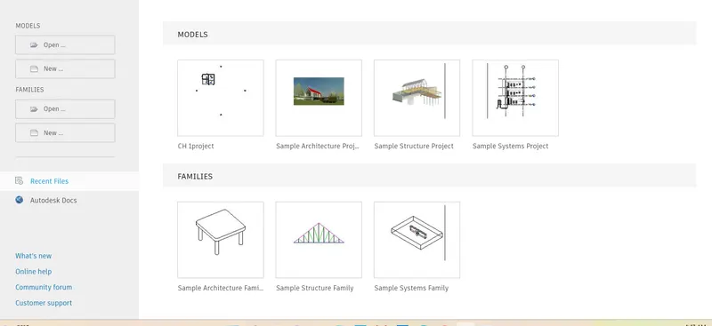
- Start with the revit
- Open a saved project from the file menu⮕
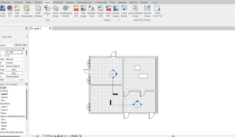
- Go to floor plan level 1 in the project browser ⮕
- Go to insert toolbar ,in the load from library there is an option for load family⮕
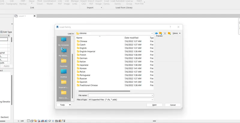
- click on that ⮕a library file from revit will get open
- choose any element from the categories⮕double click on the element⮕
- use the cursor to place the element in the model space.
Results:- The snaps of the procedure is as follows.
3) Setting up a Project – Open a project file with architectural template. Save the file with appropriate name. Set up the project units to Imperial / Metric based on your convenience of modelling. Complete the project information under Manage tab. Set up the maximum backups for project file to 3.
Aim:- Setting up a project with architectural template and setting up with the required units for the modelling, and also fill the project information and create backups for the project file.
Procedure:-
- Get Started with the revit software.
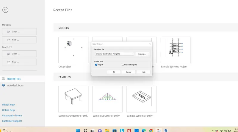
- Go with the new in the file menu and create a project file with Imperial-Architectural-template⮕ Now, the revit screen is ready with the model space
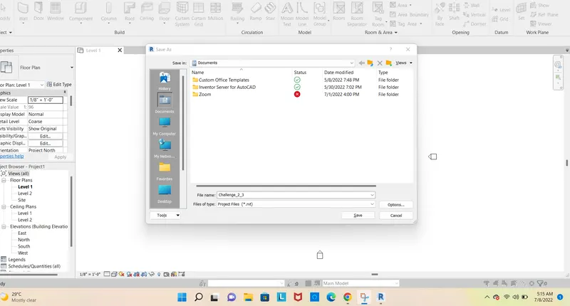
- Go to file menu and Saving the file with an appropriate name.
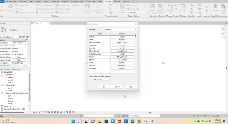
- Now Setting up with the project units⮕Go to Manage toolbar,there in the settings a tab for projects units ⮕clicking over that and get setting up with the desired units.
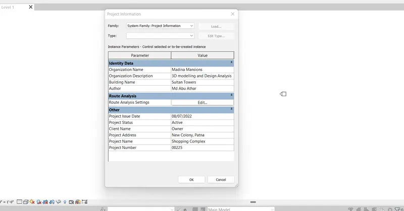
- Now,to enter the project information⮕Go to Manage toolbar,there in the settings a tab is available for the project information ⮕clicking over that and enter the required information in the fields provided.
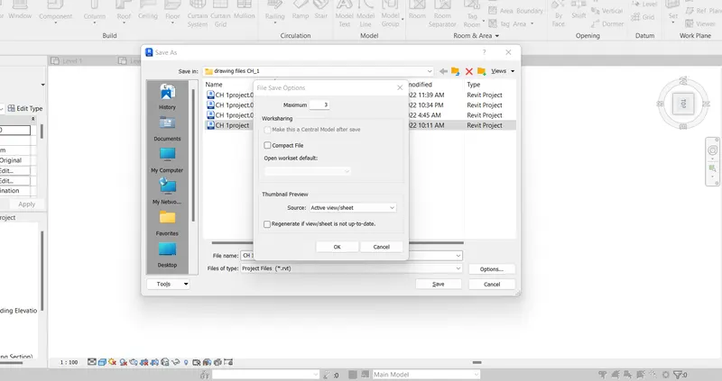
- Now, to create maximum backup file for the project⮕Go to File and click over that then,go to save as a dialouge box will get appear where options tab will be there click over the options a dialouge box will get appear fill 3 in maximum tab and press ok⮕the backup file will be created.
Results:- The snaps of the procedure is as follows.
4) Understand the concept of Levels and Grids. Follow the naming and conventions. Create the following Levels: ( Convert to metric equivalents if metric is your units)
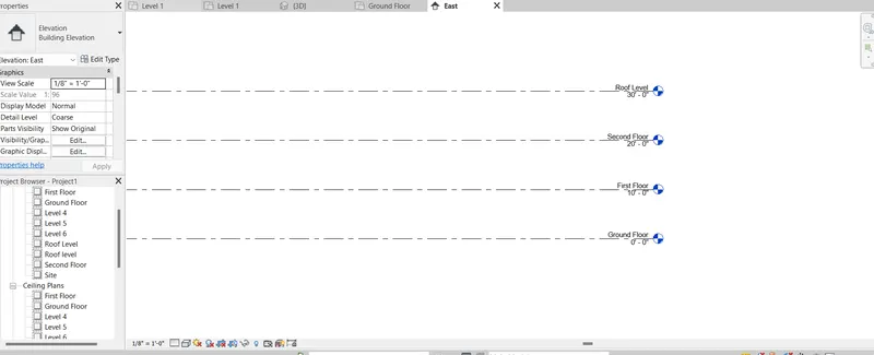
Ground Floor @ 0’
First Floor @ 10’
Second Floor @ 20’
Roof @ 30’
Grids Transverse Grids A, B,C,D, E @ 10’ spacing
Longitudinal Grids from 1 to 10 @ 20’ spacing
Aim:- To develope the concept of levels and grids and to create the levels from the given data in revit softwatre.
Introduction:-
Levels-In revit levels can be navigted from project browser and can be accessible only in elevation mode and the use of level is to see the elevation of the model of different components,that is we can create levels and can be named for that level like in building model there atre different levels like sill level,lintel level, floor level.So,on placing the elements we can connect them from one level to another level, the levels in project browser is so user friendly that if anything is mistakenly drawn in incorrect level then, it can be easily rectified by editing.
Grids- Grids are just lines with a tail having its description which is editable and are drawn to show the diviosion of the plot area.
Procedure:-
- Get Started with the revit software.
- Go with the new in the file menu and create a project file with Imperial-Architectural-template⮕ Now, the revit screen is ready with the model space
- Go to file menu and Saving the file with an appropriate name.
- Now Setting up with the project units⮕Go to Manage toolbar,there in the settings a tab for projects units ⮕clicking over that and get setting up with the desired units.
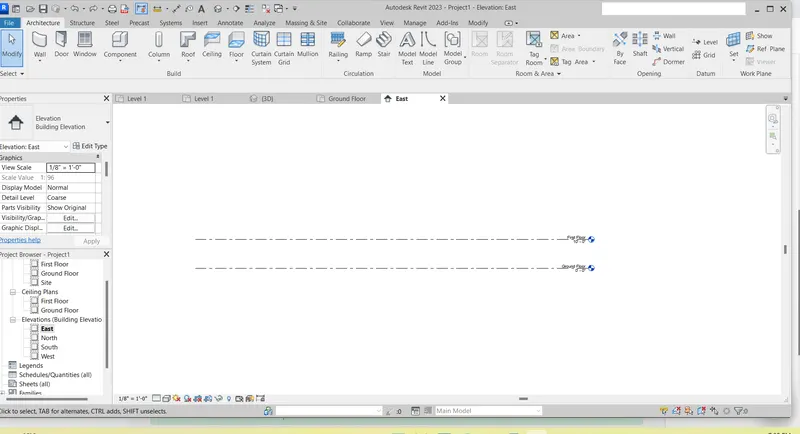
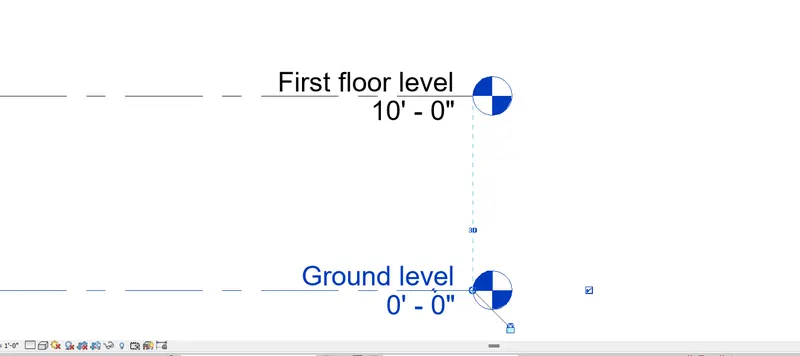
- Now, To create levels⮕Go to elevations from the project browser as levels can be provided only in the elevations⮕By default two levels as level 1and level 2 is already created at a difference of 10'⮕By taking the refrence of the created lavels create the levels by choosing level form Datum tab⮕use pick lines and give the offset as 10' ⮕Rename the levels as per your convenience.
- Now,To create Grids⮕Go to Floor Plans as grids can be marked either on floor plans or in ceiling plans⮕Choose grid from datum tab and draw a grid using line in transverse and longitudnal axis as a reference and make the changes in the naming of line in the refrence grid itself so that the next drawn grid with that refrence has the name according to that⮕using that reference line use pick lines and give the required offset and mark as many grid lines you want.
Results:- The snaps of the procedure is as follows.
5) 3D modelling of residential unit – From looking at your house / or a place you aspire. Create a conceptual layout of the residential unit. You can measure using a tape or
you can access your residential plan to create a similar layout
Aim:- To create a residential plan layout in Revit.
Procedure:-
- Start up with the revit software.
- Create a new project file in Imperial_Architectural_Template from the file menu.
- Now,the model space gets opened⮕Go to manage tab ⮕there ia an option for project units⮕set the project units as to work in feet and inches.
- Go to levels in the project browser⮕set the level 0'0'' as ground floor or setting up the required levels.
- Now,Go to Floor plans in project browser⮕Choose wall from architectural tab and create a duplicate wall of 10''.save with the name as generic 10'' and use the same for drawing the plan layout.
- Get done with arrangements of different components of the layout.
Results:- The snaps of the procedure is as follows.
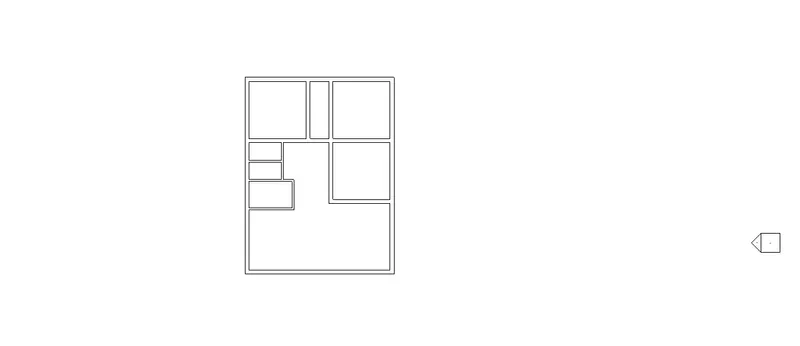
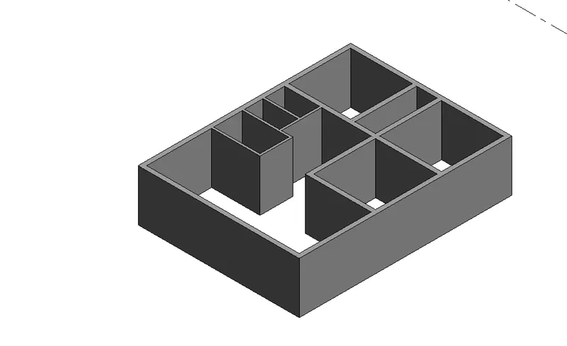
6) In the layout created draft the level of details you are planning to include – Dimensions of room, components you plan to add in the residential unit.
Aim:-To include the level of necesary details in the layout created like dimensions of room, components to add in the residential unit.
Procedure:- Get start with the Revit and open the project file drawn for the last question. from file menu.
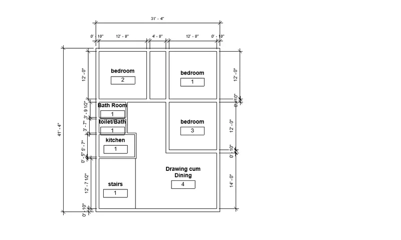
- To mark the annotations that is dimensioning of the created layout.
- Go to Ground floor level from the project browser.
- Now,Go to annotate tab choose linear to dimension the linear segments and aligned the for aligned segments.
- To provide room tags to designate the division of area of the plan layout.
- Choose Room available in Room & Area in Architectural tab and selecting it and hover the cursor on the room area and place the tag⮕Suitably edit the text also to designate particular area division.
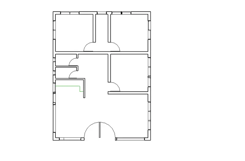
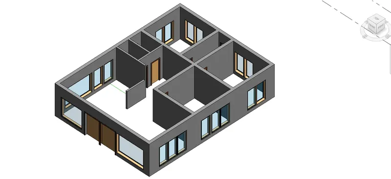
- Placing door and windows at the required locations.
- Choose the door from Architectural tab of build section and place them at the required locations,It can be placed by hovering the mouse on wall in the ground floor view of plan layout.
- If any special size of door is required which are not available in family library then create duplicate element,name them and change the dimensions.
- similarly place the windows.
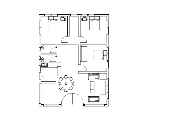
- Placing the components in the layout⮕Go to Component of build in Architectural tab⮕load the components from tghe library family and place them to the desired locations.
Results:- The snaps of the procedure is as follows.
- Getting srtarted with the Revit.
- Dimensioning of the plan layout.
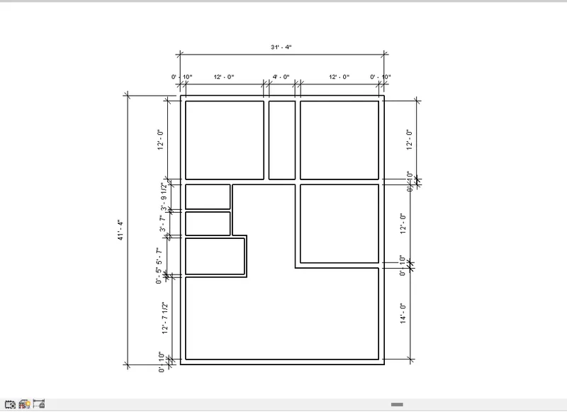
- Providing the room tags to show the area division of the layout.
- Placing of door and windows in the 2D view.
-
- Placing of door and windows in the 3D view.
- Placing the components in the layout.
7) Identify the residential model elements such as Door, Windows, Tables, Chair, Couch, Bed, Lamps from the library and insert them to the model . Save the project for use
for Assignment 3
Aim:- To place the different components such as Door, Windows, Tables, Chair, Couch, Bed, Lamps from the library and insert them to the model .
Procedure:-
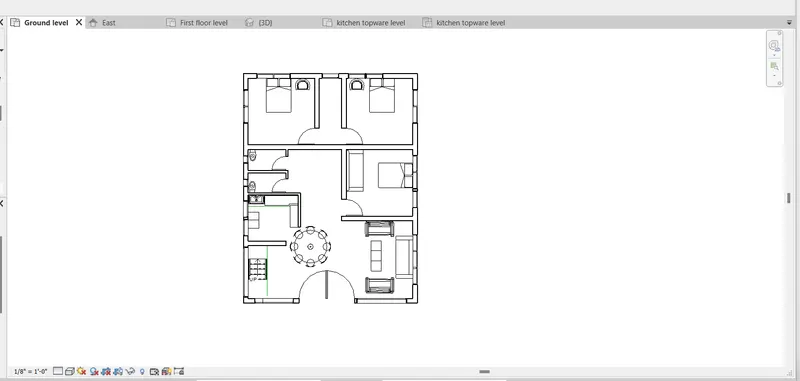
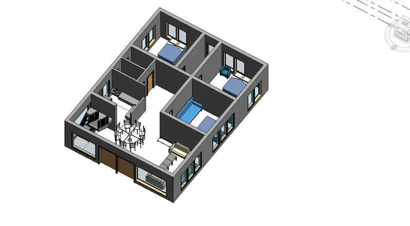
- Get Start with the project file drawn for the last assignment ⮕Go to floor plan⮕Go to Component of build in Architectural tab
- load the components from the library family.
- choose the elements as it is feasible with the size of rooms or any area.
- place the components to the convenient locations.
Results:- The snaps of the procedure is as follows.
- Placing the components in 2D view
- Placing the components in 3D view
- placed components View, after providing roof finally.