Creation of geometries by Coordinate system methods using AutoCad
Aim:-
The aim of the project is to draw the different geometries given using different coordinate system methods specified.
Introduction:-
The types of coordinate systems available ton use in the autocad are as follows:-
- Absolute coordinate system method:- This is a kind of coordinate method which Auto cad supports to draw the geometries in which a whole cartesian coordinate system is reference and (0,0) is the origin and different coordinate values of the geometry in x and y shall need to be provided.
- Relative coordinate system method:- This is a kind of coordinate method which Auto cad supports to draw the geometries in which the coordinates are provided in such a way that for the first point the relative coordinate is origin and in the same way for all the next coordinates values previous coordinate will be relative coordinate so, the next coordinate values are entered taking previous coordinate as the reference.
- Relative rectangular coordinate system method:-In this method of geometry drawing the first point is given or entered with respect to the absolute coordinate system then the next points are specified by taking @x,y i.e., next points are at what distance from the first absolute point either in x y or in (-x) and (-Y).for @X it means that moving in positive x direction from absolute point,for @Y it means that moving in positive Y direction from absolute point,@-X (or)@-Y means that moving in x and y in negative direction from the absolute point.
- Relative polar coordinate system method:This is also a relative coordinate method in which distance and angle both are introduced and it is entered in such a way that @distance<angle. The distance will be measured from the absolute coordinate point and the angle takes the reference of quadrant.
Procedure:-
The fig P1 and P2 are need to be drawn using all coordinate system method. All coordinate system means or specifies that the geometries needs to be drawn using all the coordinate system methods available in the Auto Cad.
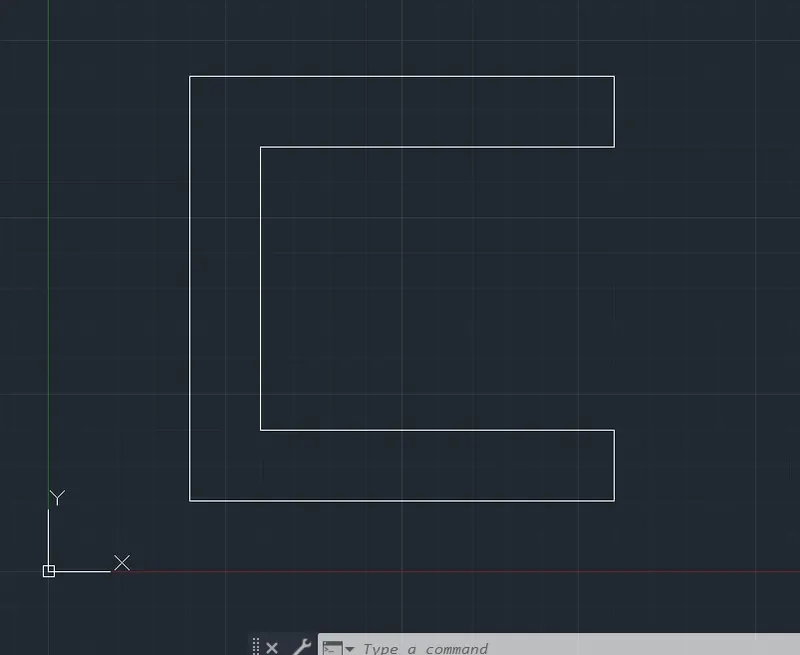
- To Draw P1 using Absolute coordinate method
choose the line tool from the draw menu enter⮕giving coordinates as (2,1),(8,1),(8,2),(3,2),(3,6),(8,6),(8,7),
(2,7)⮕enter⮕close
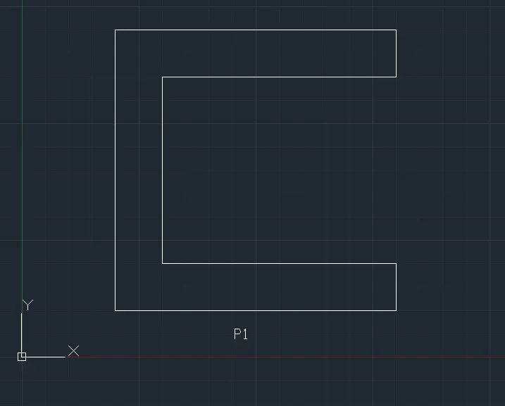
- To draw P1 using Relative Rectangular coordinate method
Give L in line coommand(enter)⮕Give the absolute coordinate valueas(2,1)then use shift @distance in X, Y
start entering the other points
as @ 6,0, @0,-1, @-5,0, @0,-4 @5,0, @0,-1
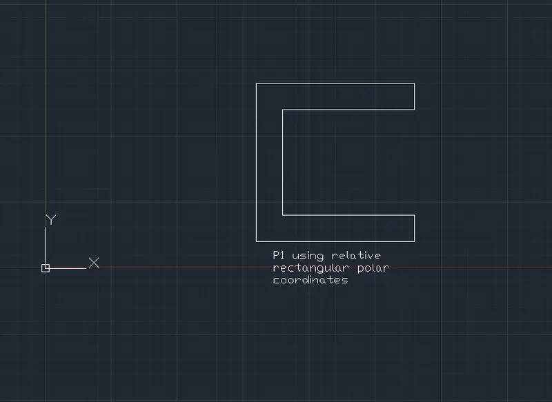
- P1 using polar coordinate method.
Give L from the line command ⮕enter⮕line tool selected then give the absolute coordinate as the first point⮕(2,1)⮕give the other point values in terms of length and angle as @length<angle.
@6<0, @6<90, @6<0, @1<270, @5<180, @4<270, @5<0, @1<270,
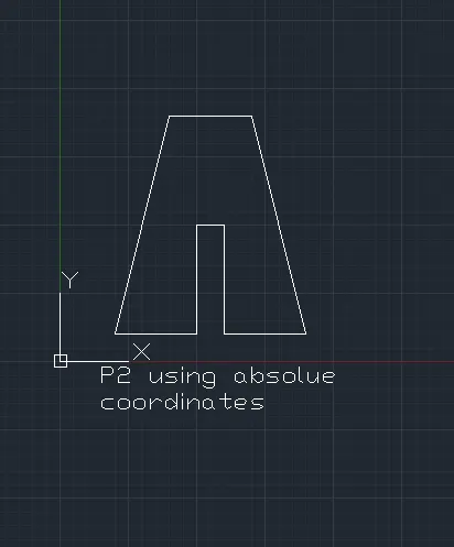
- P2 using Absolute coordinates
choose the line tool from the draw menu enter⮕giving coordinates as (2,1),(5,1),(5,5),(6,5),(6,1),(9,1),(7,9),
(4,9)⮕enter⮕close
- P2 using Relative rectangular coordinates.
Give L from the line command ⮕enter⮕line tool selected then give the absolute coordinate as the first point⮕(2,1)⮕give the other point values in terms of length and angle as @length<angle.
other points are @2,7, @3,0, @2,-7, @-3,0, @0,4, @-1,0, @0,-4⮕enter⮕ close.
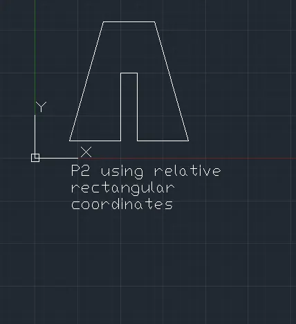
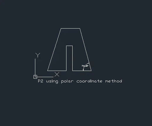
- P2 using polar coordinate method.
Give L from the line command ⮕enter⮕line tool selected then give the absolute coordinate as the first point⮕(2,1)⮕give the other point values in terms of length and angle as @length<angle.
angle calculation
√(4+49)=7.280
tanθ=7.280/2, θ=74.638
@3<0, @4<90, @1<0, @4<270, @3<0, @-7<-74.638, @-5<0,⮕close ⮕ enter
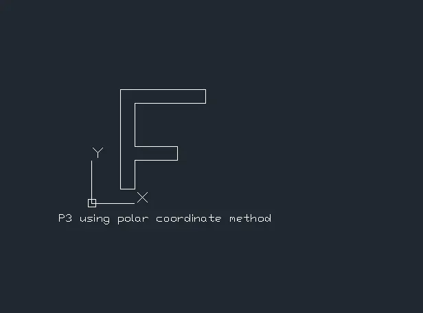
- P3 using polar coordinate method
coordinates identified from the geometry are
(2,1), @1<0,@2<90, @3<0, @1<90, @-3<0, @3<90, @5<0, @1<90, @-6<0⮕close⮕ enter.
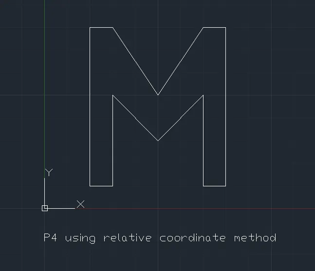
- P4 using relative coordinate method
The coordinates identified are (2,1), @0,7, @1,0, @2,-3, @2,3, @1,0, @0,-7 @-1,0 @0,4, @-,-2, @-2,2, @0,-4 ⮕close⮕enter
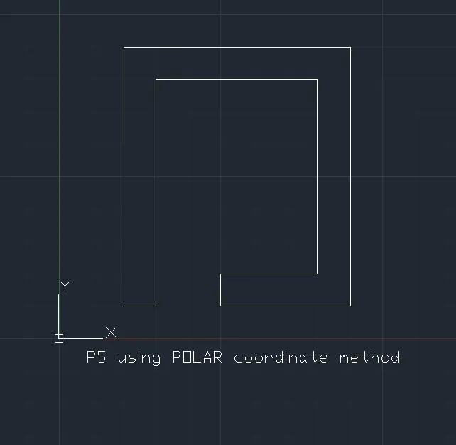
- P5 using Polar coordinate method.
select the line tool from the draw panel ⮕specify the first absolute coordinate as(2,1) then
the polar coordinate for the given geometry is identified as @1<0, @7<90, @5,0, @6,270, @3,180, @1<270, @4<0, @8<90, @7<180 close ⮕enter ⮕exit
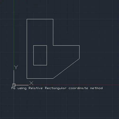
- P5 using Relative rectangular coordinate method
select the line tool from the draw panel ⮕specify the first absolute coordinate as(2,1) then
using relative rectangular coordinate method the coordinates are @4,0, @4,3, @0,2, @-4,0, @0,4, @-4,0
after completing the above cooordinates choose rectangle from the draw panel and specify its first point as (3,3) and second point as (5,6)⮕exit
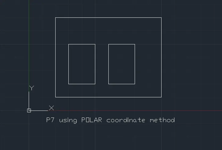
- P7 using Relative polar coordinate method.
select the line tool from the draw panel ⮕specify the first absolute coordinate as(2,1) then
the relative polar coordinates are @2<0, @3<90, @2<180⮕close
now, for the left rectangle ⮕(3,2), @2<0, @3<90, @2<180⮕close
for the right rectangle ⮕(6,2),@2<0, @3<90, @2<180⮕ close.
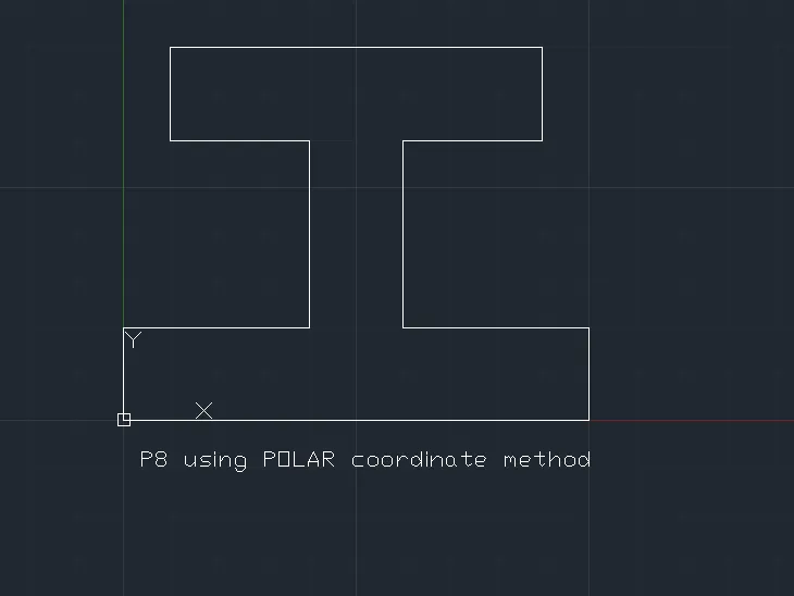
- P8 using Relative polar coordinate method
select the line tool from the draw panel ⮕specify the first absolute coordinate as(0,0) then
the relative polar coordinates are @(10<0),@(2<90),@(4<180), @(4<90), @(3<0),@(2<90), @(8<180), @(2<270), @(3<0), @(4<270), @(4<180), @(2<270).
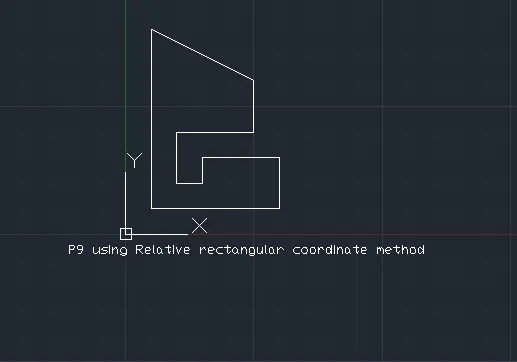
- P9 using Relative Rectangular coordinate method.
select the line tool from the draw panel ⮕specify the first absolute coordinate as(0,0) then
using Relative rectangular coordinate method the coordinates are @(0,7), @(4,-2),@(0,-2),@(1,0), @(0,1), @(3,0), @(0,-2), @(-5,0)
- P10 using relative Polar coordinate method
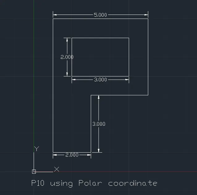
select the line tool from the draw panel ⮕specify the first absolute coordinate as(1,1) then
using relative polar coordinate the coordinates identified from the geometry are @(2<0), @3(3<90), @3<0), @(4<90), @(5<180), @(7<270).
again using absolue coordinate (2,5) for rectangle then, the polar coordinates are @(3<0), @(2<90), @(3<180) ⮕enter⮕close.
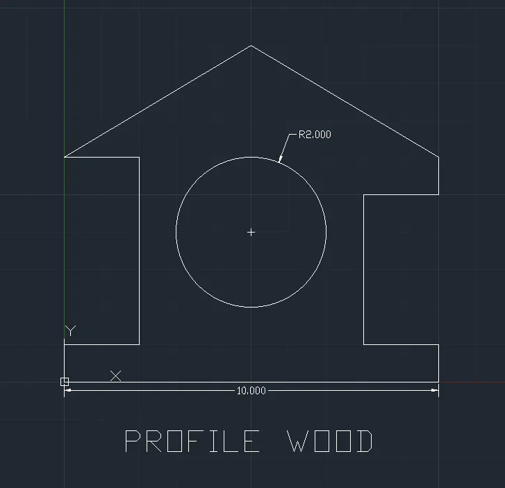
- To Draw the civil related drawings there are no specific methods are specified so drawing these with the help of mix coordinates like whichever coordinate are required at the instance are used.
For PROFILE WOOD,
the coordinates identified from the geometry are (0,0), @(10<0), @(1<90), @2<180), @(4<90), @(2<0), @(1<90), @(5.831<149.036), @(5.831<241.928), @(2<0), @(5<270), @(2<180)⮕close⮕enter
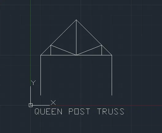
- To draw Queen post truss as in the given geometry.
For QUEEN POST TRUSS,
the coordinates identified from the given geometry are(1,1), @(4<90), @(5<45), @(5<-45), @(1<180), @(1<90), @(2.536<180), @(3.53<90), @(2.536<180),@(1<90)⮕some left portions are drawn free hand.⮕
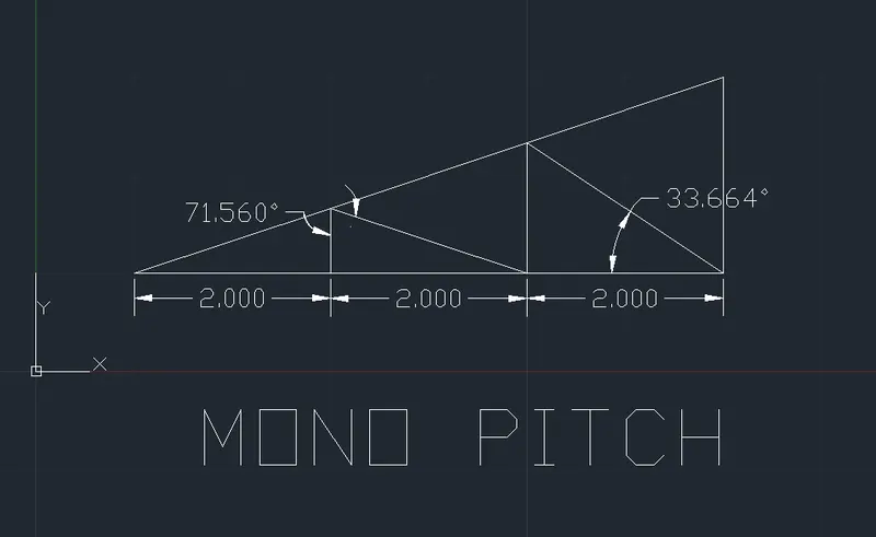
- For MONO PITCH,
angle calculations
cosθ=2/2.108=θ=18.44deg, cosθ=2/2.403=θ=33.664deg.
the coordinates identified from the given geometry are(1,1),@(2<0), @(2<0), @(2<0), @(2<90), @(-2,-0.667), @(2,0.667), @(2.108<-18.44), @(1.333<90), @(2.403<33.664)⮕enter ⮕ close.
Result:-
Resultant image of the each of the geometry input are attached one after another of the selected geometry.