Creating 3D Isometric view of various structural elements in AutoCAD
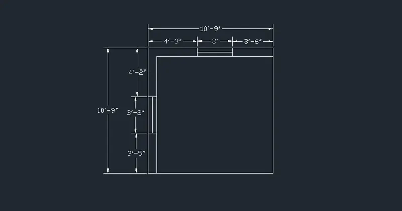
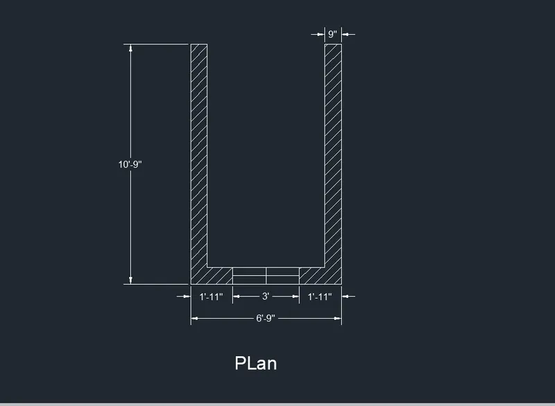
1. Create a 3D Isometric View of the building with plan and elevation given.
Aim:- To Create a 3D Isometric view of the building using the given plan and elevation as shown in the Figure:-
Introduction:-Creating a 3D model, the progression is in such a way that
- wireframe models- creating wireframe models using lines.
- Surface-Surfaces are created from the enclosed wireframes.
- solid- Solids are created from surfaces.
Procedure:-
- Start with the autocad⮕ set the unit type as Engineering with the precision 0'0'' and the insertion unit as inches⮕analyse the screen required for the drawing and set the screen size using limmax⮕Zoom⮕ all⮕ now the screen is ready for the drawing.
- Switch the workspace to 3D basics and keep the screen in top view.
- First drawing the given plan and elevations.
- The plan and elevation can be drawn in 3D basics itself and in the top view.
- Take the Snap of the plan and elevation in top view.
- In the top view itself use the command extrude to give the elevation to the wall drawn in 3D.
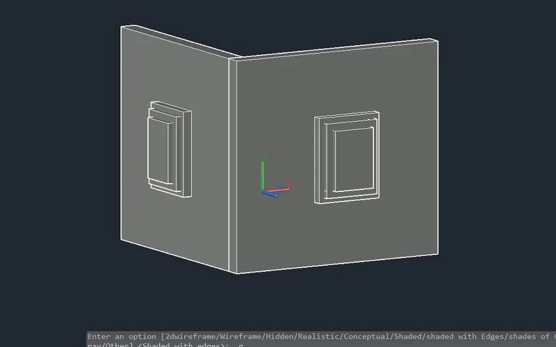
- Create the window on the wall face as per directed in the elevation plan.
- To create window select the face using "ucs"⮕face.⮕Draw the detailing of the winow on the selected face⮕create the region from the same ⮕now,Substract the window as rectangle from the wall face as the bigger rectangle.
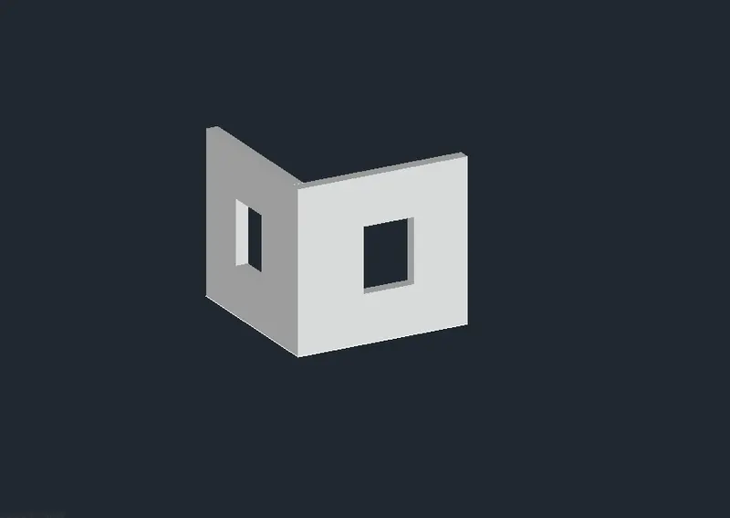
- Do same for the adjacent wall.⮕Take the snap of the model in 3D after creating window.
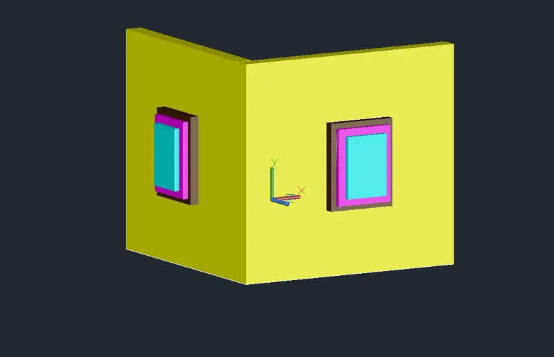
- Now,Provide colours to the wall,window panels so that the different components can be distinguished well.
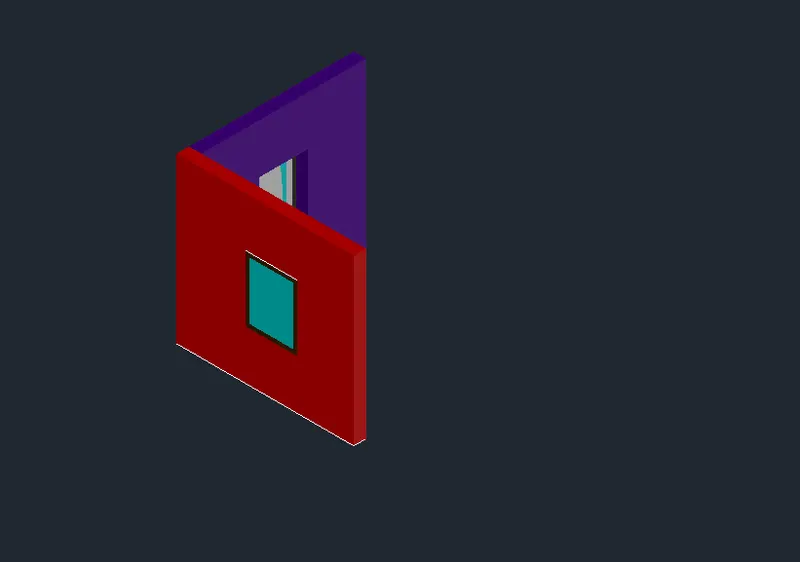
Results:- The Snaps of the model created are as follows.
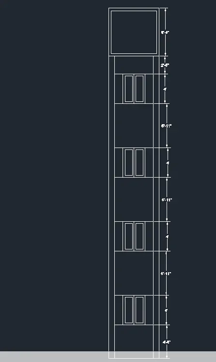
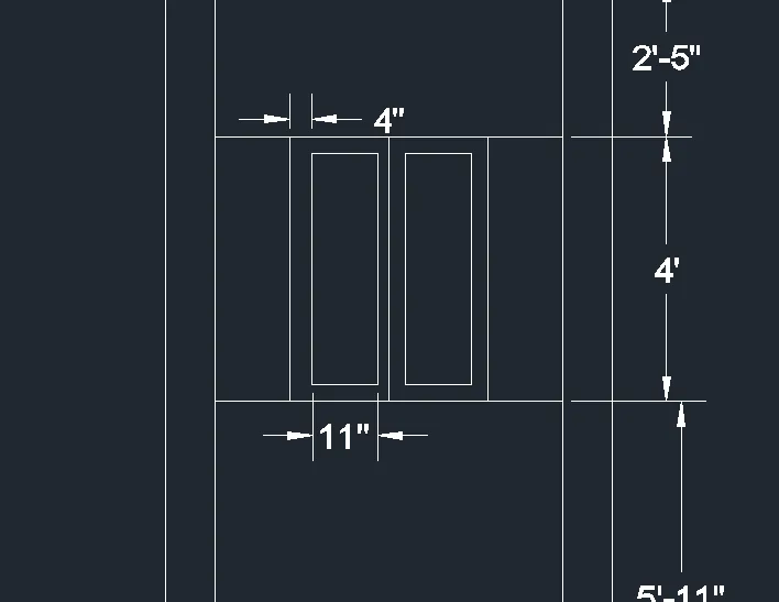
2. Create the 3D View of the Building Façade as given in the plan and elevation. Also, see the detail of the window.
Aim:- To Create a 3D view of the building using the given plan and elevation as shown in the Figure:-
Introduction:-Creating a 3D model, the progression is in such a way that
- wireframe models- creating wireframe models using lines.
- Surface-Surfaces are created from the enclosed wireframes.
- solid- Solids are created from surfaces.
Procedure:-
- Start with the autocad⮕ set the unit type as Engineering with the precision 0'0'' and the insertion unit as inches⮕analyse the screen required for the drawing and set the screen size using limmax⮕Zoom⮕ all⮕ now the screen is ready for the drawing.
- Switch the workspace to 3D basics and keep the screen in top view.
- First drawing the given plan and elevations.
- The plan and elevation can be drawn in 3D basics itself and in the top view.
- Take the Snap of the plan and elevation in top view.
- In the top view itself use the command extrude to give the elevation to the wall drawn in 3D.
- The elevation of the wall is given but herein it required to provide winows at different levels so the wall face using "UCS,face" to work on the particular face.
- Create the window on the wall face as per directed in the elevation plan.
- The window portions are substracted from the wall as wall acts as the bigger rectangle while windows are smaller rectangle.
- use copy selection with a snap point⮕and also create intersection points on the wall face where it is require to place the windows⮕ and copy the windows at the required levels
- Create the window on the wall face as per directed in the elevation plan.
- The window portions are substracted from the wall as wall acts as the bigger rectangle while windows are smaller rectangle.
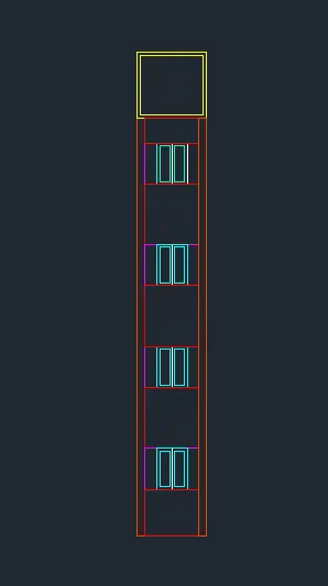
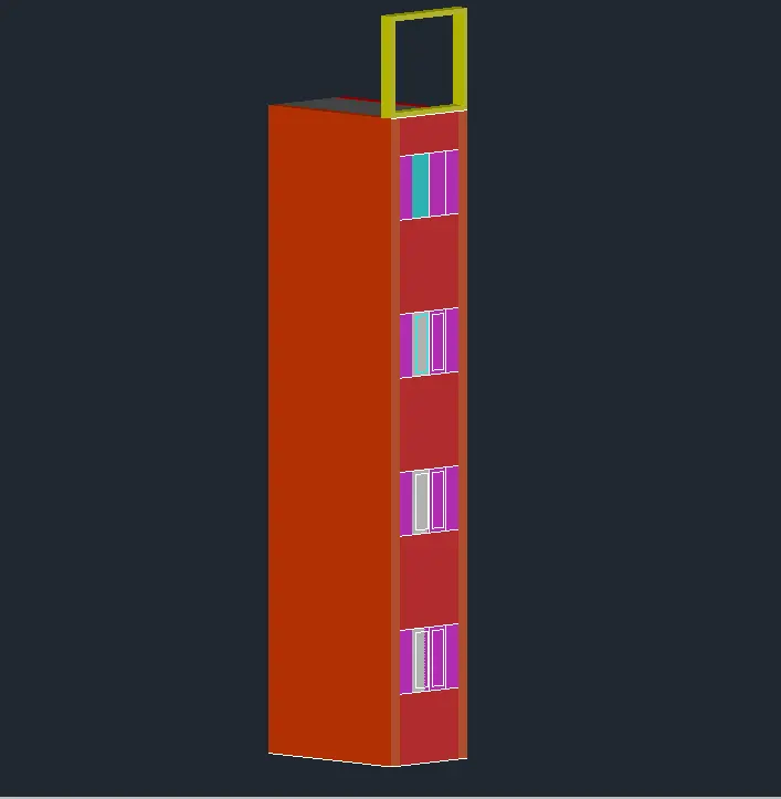
- Creating various rectangles on the wall face to create different regions to give different colors so that the elevation can be more and more distinct.
- Take the snaps of the model.
Results:- The Snaps of the model created are as follows.
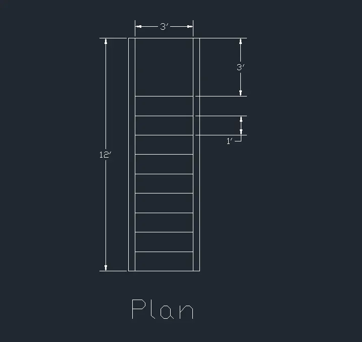
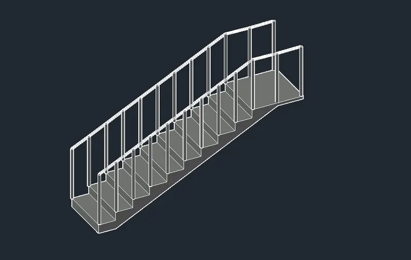
3. Create the ismoteric 3d view of a stair with railing as shown in the plan and elevation. Assume the size of the balustrades and the hand rails.
Aim:- To Create a 3D view of a stair with railing using the given plan and elevation as shown in the Figure:-
Introduction:-Creating a 3D model, the progression is in such a way that
- wireframe models- creating wireframe models using lines.
- Surface-Surfaces are created from the enclosed wireframes.
- solid- Solids are created from surfaces.
Procedure:-
- Start with the autocad⮕ set the unit type as Engineering with the precision 0'0'' and the insertion unit as inches⮕analyse the screen required for the drawing and set the screen size using limmax⮕Zoom⮕ all⮕ now the screen is ready for the drawing.
- Switch the workspace to 3D basics and keep the screen in top view.
- First drawing the given plan and elevations.
- Using the line command in the top view drawing the elevation of the stairs ⮕ The progression of drawing goes as riser is 6'',tread is 1' while the landing is 3' as directed in the question.The assumed dimensions are width of the stair as 3' wiode while the height of balustrade as 3' high.
- Using the extrude command the 2D model of the stair is extruded widhwise as 3' wide.
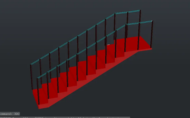
- using a circle on each trade extrude it in z axis as 3' for balustrades ,providing railings also on it and the same is copied on the other side.
- providing different colors and shade to each component of the stair for the distinguished visualisation of the stair.
Results:- The snaps of the progression of the drawing are as follows:-
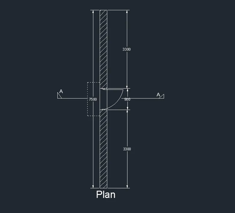
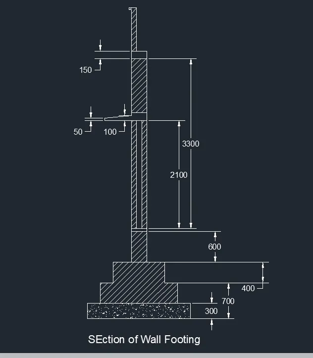
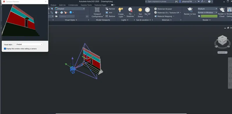
4. Create the 3D view of a Wall with spread footing . Create the Door opening only. Assume the size of the parpaet and the coping. See the plans and elevation for the details. Also, create a rendered view of the model with materials as of your choice.
Aim:- To Create a 3D view of a wall with spread footing using the given plan and elevation as shown in the Figure:-
Introduction:-Creating a 3D model, the progression is in such a way that
- wireframe models- creating wireframe models using lines.
- Surface-Surfaces are created from the enclosed wireframes.
- solid- Solids are created from surfaces.
Procedure:-
- Start with the autocad⮕ set the unit type as Engineering with the precision 0'0'' and the insertion unit as inches⮕analyse the screen required for the drawing and set the screen size using limmax⮕Zoom⮕ all⮕ now the screen is ready for the drawing.
- Switch the workspace to 3D basics and keep the screen in top view.
- First drawing the given plan and elevations with the given dimensions in top view.
- Switch to front view and extrude the plan to the required width.
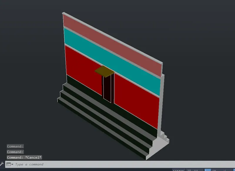
- Select the face on which you want to provide the sunshade and door ⮕Draw rectangles for the same and extrude them to visualise them for door and sunshade.
- Give different colors to the different faces for the distinct visual.
- Get the snap of the drawing in 3D view.
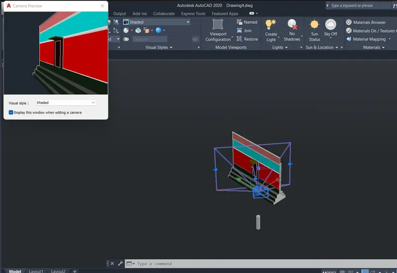
- Now,for rendering create different views using camera⮕name them and save them.⮕view can be used for rendering.
- using RMAT add the different materials in the docuyment file.
- using Attachmaterial provide different materials to different components of the wall.
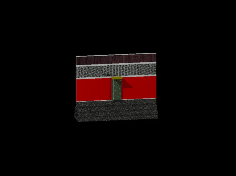
- render the wall in medium quality and save the snap.
Results:- The snaps of the progression of the drawing are as follows:-