Project 1_Comparative study of different storey buildings for Seismic forces
Project 1
Factors influencing the Natural Period of a building.
Aim:- To model Structural Moment Resisting frames with different structural feaures mentioned from model A to model K.
Procedure:-
1. Model A
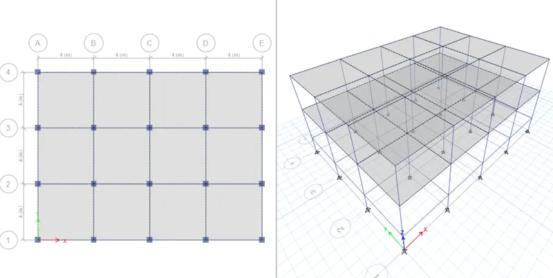
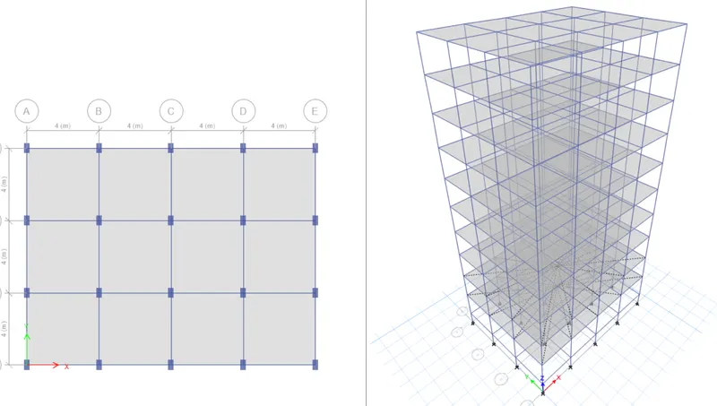
Model A consists of two storey building frame with four number of bays in X direction and three number of bays in Y direction,the column size of the frame is 400X400 while the beam size is 300X400 respectively.
- Stepwise procedure for model A
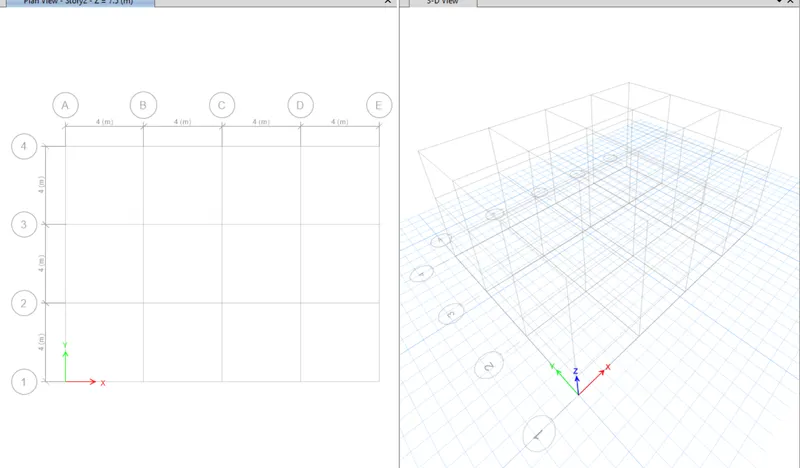
- Creating the Grid System of the frame.
- Get open with the Etabs software and Go to file menu bar to create a new model.
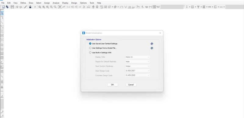
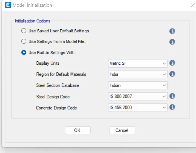
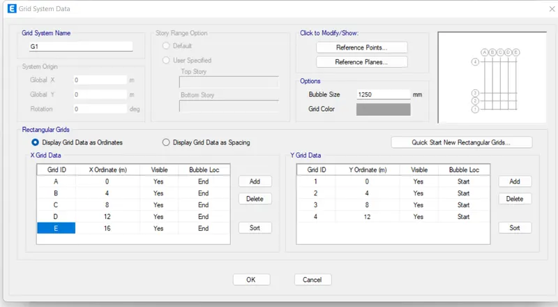
- A dialouge box will get open as model initialization, select use built in settings and add the required provisions tap ok⮕ A new dialouge box will get open as New model quick template⮕select custom grid spacing and go to edit grid data ⮕define the grid spacing in X and Y direction ⮕tap ok.
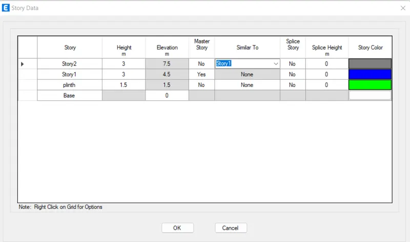
- on the right side of New model quick template select edit story data⮕make the required changes,remove the unnecessary default stories and define the stories as base,plinth ,story 1,story2 and make the story 1 as master story and story 2 as similar to story 1⮕tap ok.
- The Grid system of the frame is created now.
- Define the section materials and section properties.
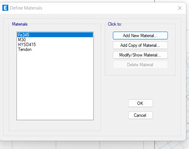
- Go to define tab under which choose material properties.
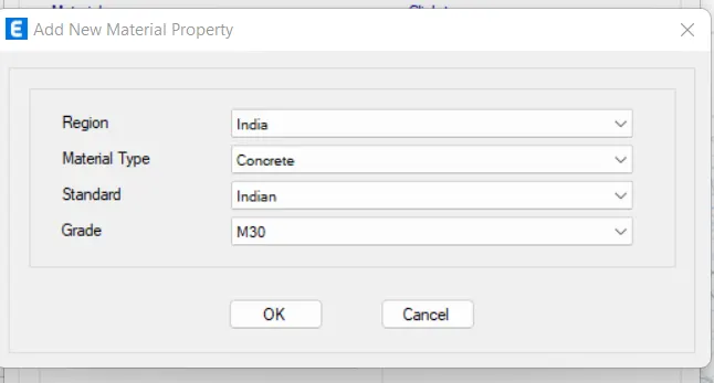
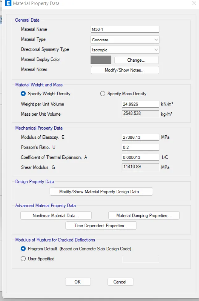
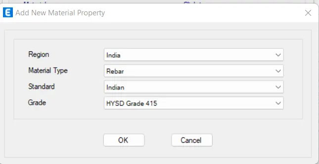
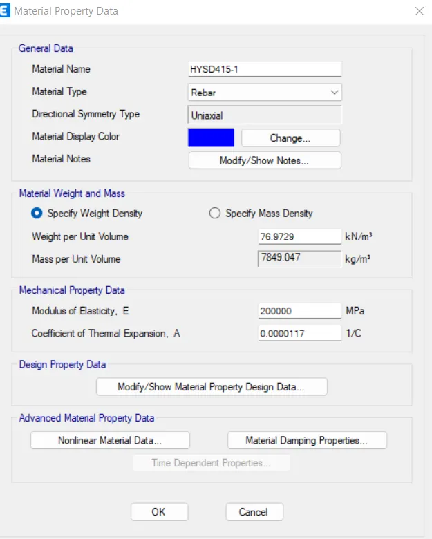
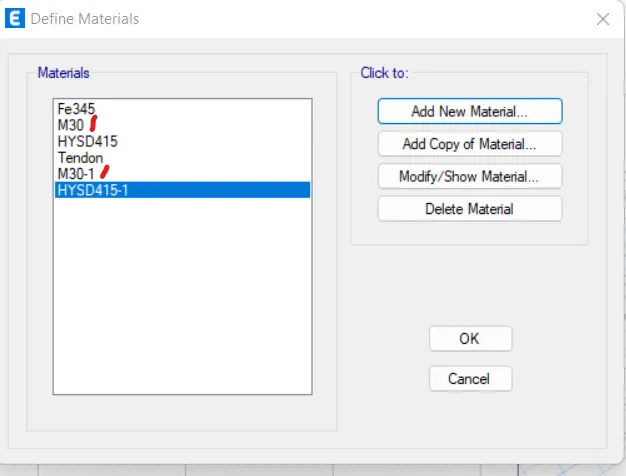
- A new diaoulouge box will get open as define materials choose to add new material then add Concrete as M30 grade concrete and rebar as HYSD 415 with the indian standards.
- Define the section properties.
- Go to define tab under which choose section properties.
- To define the section properties of beam and column go to frame sections and for slab go to slab sections.
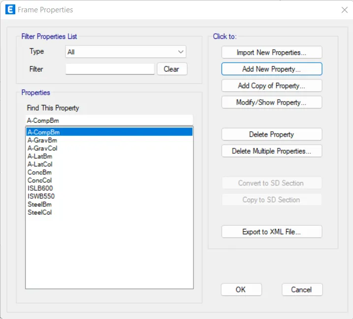
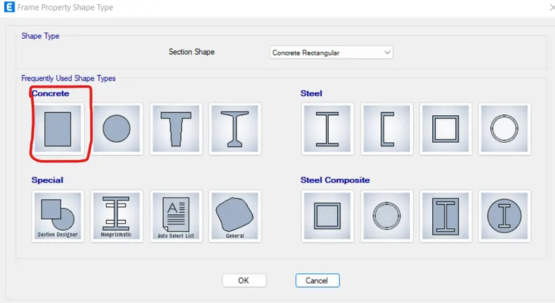
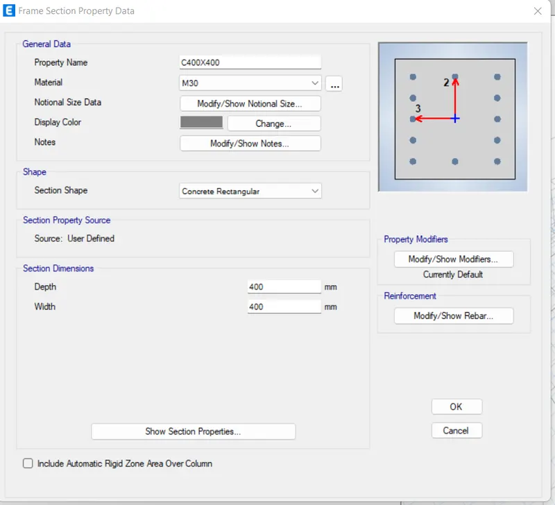
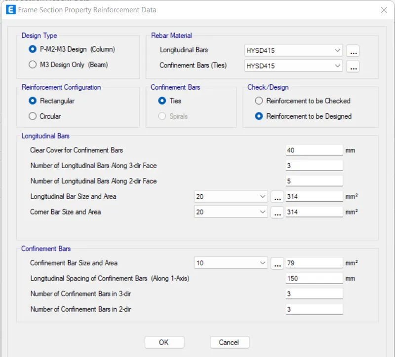
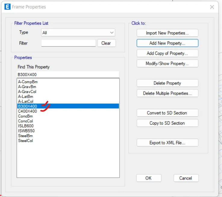
- Under frame sections select to add new property⮕give the name of the property⮕select the material type⮕Give the section dimensions and perform the required changes in Modify reinforcement tab.
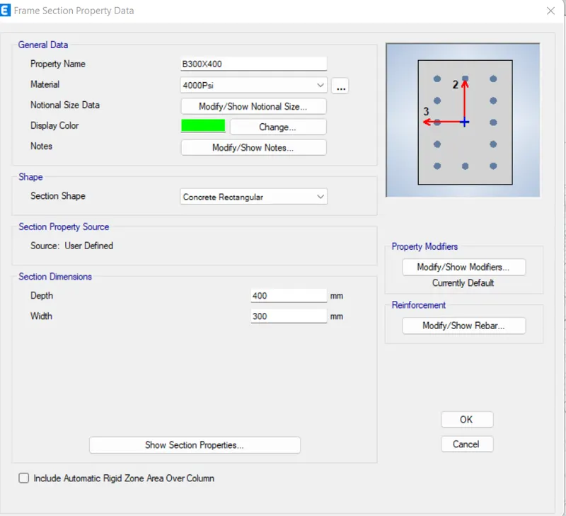
- Similarly define the beam section with their respective dimensions.
- Under slab sections select to add new slab⮕rename the slab as per yours feasibility⮕slab material as M30⮕modelling type as membrane⮕define the thickness ⮕tap ok.
- Add Load Patterns
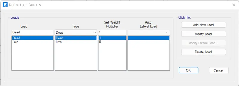
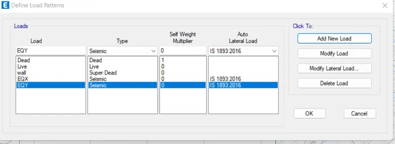
- Go to Define tab under which choose load patterns and the loads like wall as superdead and EQX and EQY seismic load under codal provisions of IS 1893:2016,adding them apart from the existing dead and live load.
- Tap ok.
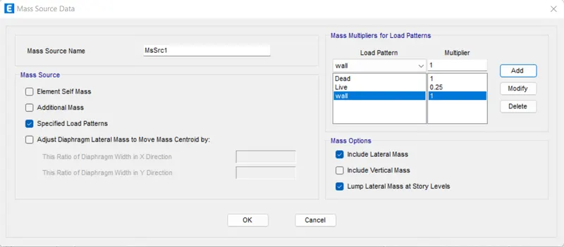
- Define Mass source.
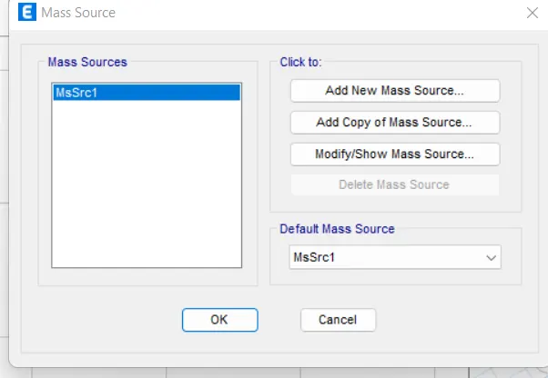
- For defining the mass source again go to define tab under which choose mass source option.
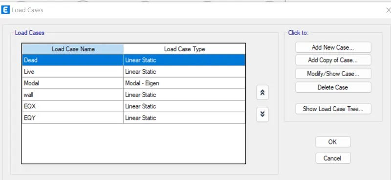
- Check for the load cases added.
- Define the Load combinations:-
- Go to define tab under which choose load combinations.
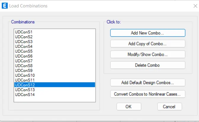
A dialouge box will open as load combinations under which select Add default design combinations then in the tab select for concrete frame design and also select convert to user combinations editable then the load combinations will get appear.
- select all of them press ok.
- Start,Modelling of the frame that is assigning section properties to the grid system.
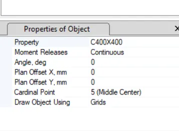
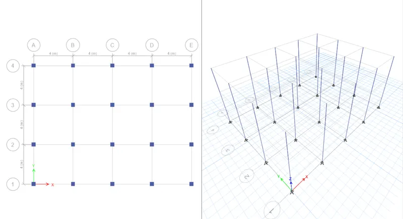
- Select quick draw columns from the tool panels available at the left side of the model space.
- As the column has to run from base to the top, all stories option shall must be checked out.
- Place the columns at each intersections of the grid.
- View the assignment of column to the model in 3D view also to avoid any kind of glitch at the later stage.

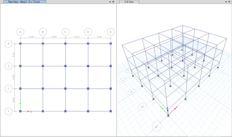
- Similarly select the quick draw beams option from the tools available at the left of the model space.
- As the beams also needs to be placed from the base to the top grid lines all stories option shall must be checked out.
- Select the defined property of beam and place them at each of the grid lines.
- View the assignment in 3D to make sure that it is replicated at all the required grid positions.
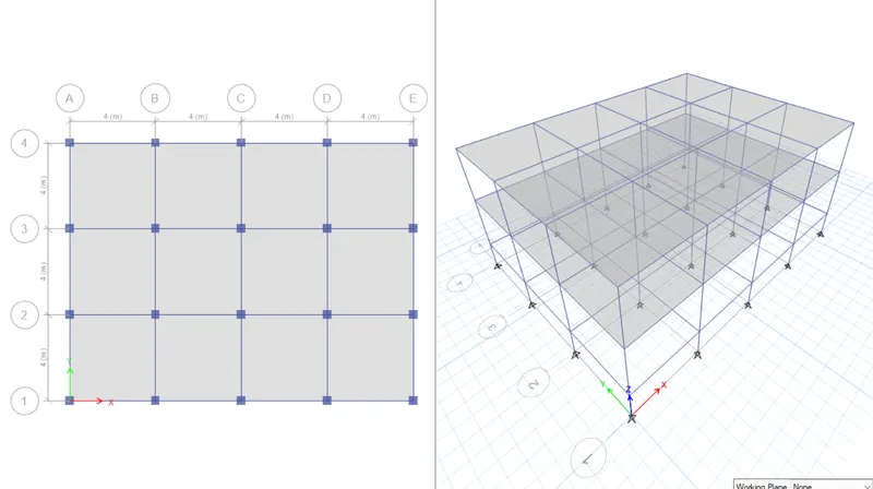
- Similarly, select the quick draw floor option and select the created property for slab.
- Take the story 1 frame into the model space and make sure that similar stories option is selected so that the same slabs should be replicated on the above floors as well.
- Now,Assign the loads.
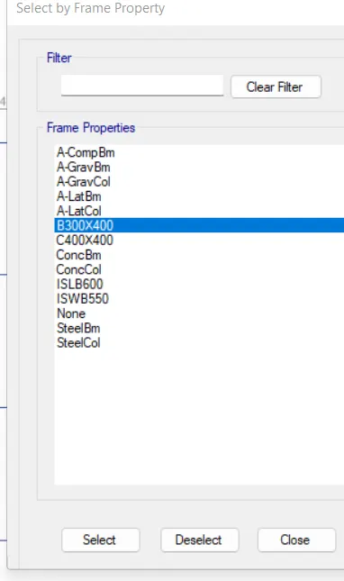
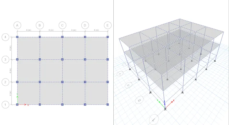
- For assigning the loads first select the member at which you want to assign the loads.
- Go to select tab under which⮕select properties⮕frame sections⮕select the beams for assigning the frame loads.
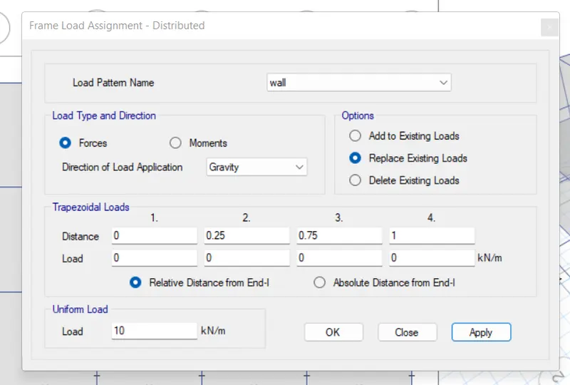
- Now,Go to assign tab under which choose frame loads⮕distributed⮕select the load pattern named defined earlier⮕Give the uniform load value⮕apply⮕ok,
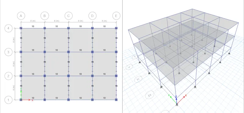
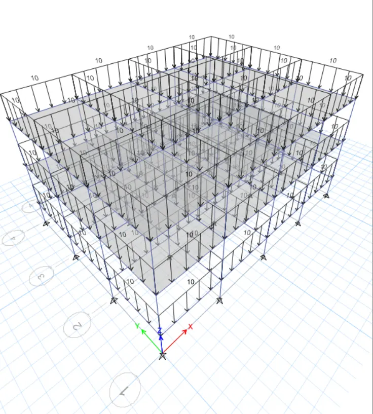
- The frame loads will be assigned to the selected frames.
- Now,assigning the live loads.
- Go to select tab⮕properties⮕slab sections⮕select the slab assigned into the model.
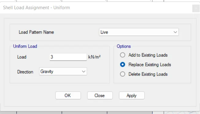
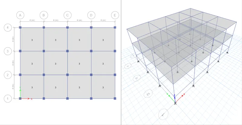
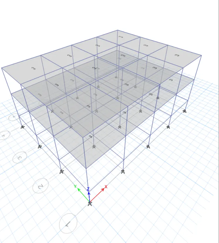
- once the slabs is selected Go to assign tab⮕shell loads⮕uniform⮕Change the load pattern to live and the give the uniform load value as 3 kn/m2.⮕apply⮕ok
- The given load shall be assigned to the selected slabs.
- Now,Assign the Diaphragm property.
- To assign the diaphragm first select all the slabs using select tab.
- Go to Assign tab⮕Shell⮕Diaphragms⮕a new tab will get open⮕select D1⮕apply,ok
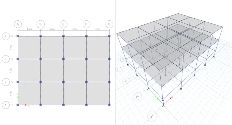
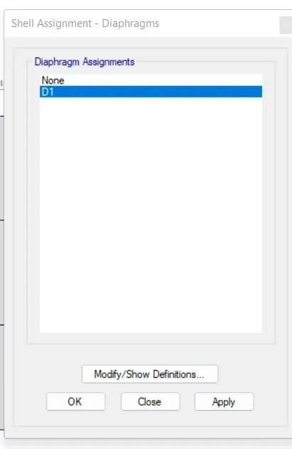
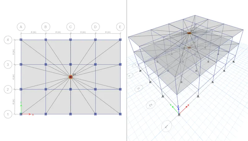
- Analysis of the model
- For performing the analysis either choose to tap the play button or press F5,the analysis process will get started.
- Wait for the system to perform analysis.
- The analysis process will get completed once model get into deflected shape or the model get locked.
- Now, we can access the analysis results.
2.Model B
In the model B, the only difference with the model A is that the model A has only 2 stories while model B has 5 stories, rest all the other structural elements are same.
Procedure:-
- The model A itself can be edited for model B.
- First save the model with the model A name.
- Again save as the model with the name as model B,now,the editing can be done.
- Go to edit tab under which select edit stories and grid systems⮕modify /show story data⮕right click on story data row and select to add story option,add three more stories into the model and make the new created stories similar to story 1.
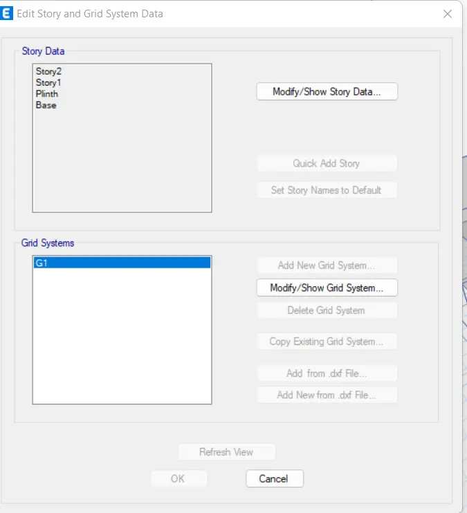
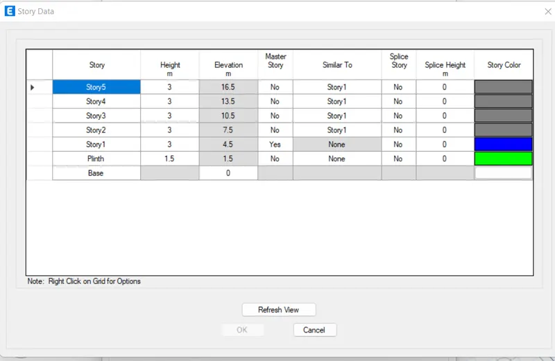
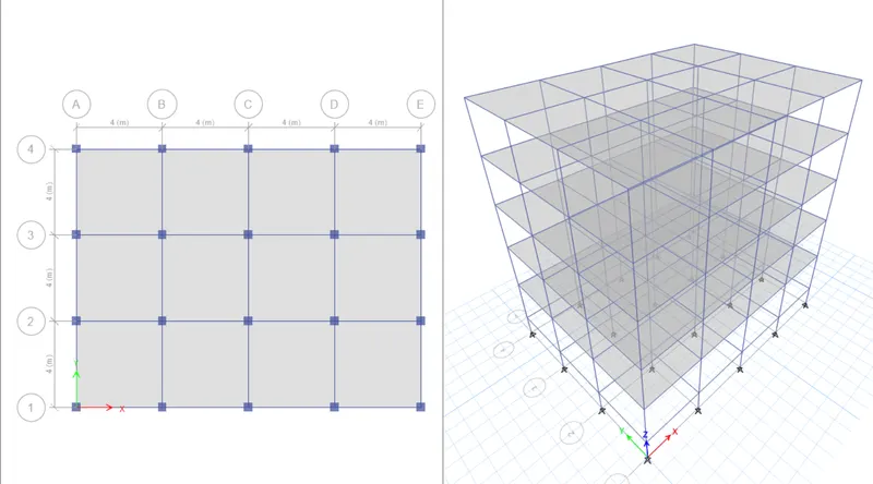
- Press F5 or the play button for performing the anaslysis of the model, deflected shape of the model will ensure the completion of analysis process .
- once the analysis is done save as the model as Model C for editing to create model C.
3.Model C
The difference between Model B and Model C is that only the column dimension is varying while all other structural features are similiar.
- Using the saved Model C for editing.
- Go to define tab and access the Column C400X400 and select the option for modify/show property.
- Change the depth and width of the column.
- Apply ,ok.
- The model shall automatically be assigned with the C550X300 of column.
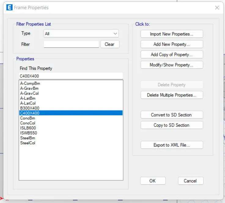
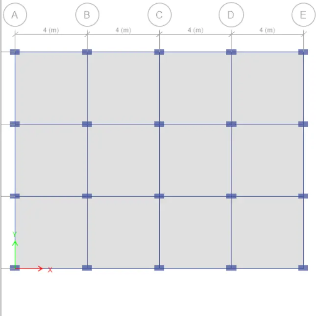
- Check for the Diaphragms in the model if it is there okay, otherwise provide it by seklecting the slabs.
- Run Analysis.
- Now save the model with save as option with the name as Model D for editing for model D itself.
4.Model D
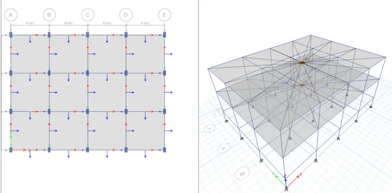
The difference between model C and model D is only that in model C the column C550X300 is oriented along x direction while in model D the same column C550X300 has to be oriented along Y direction and all other structural features of the model is same.
- To change the orientation of column.
- First change the dimension values from depth 550 to depth equal to 300 and width 300 to 550.then,
- Select all the columns whose orientation is required to be changed.
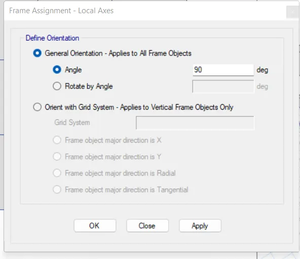
- Go to Assign⮕frame⮕local axes⮕change the angle from 0 to 90.
- Check for the Diaphragms in the model if it is there okay, otherwise provide it by seklecting the slabs.
- Run Analysis.
- Now save the model with save as option with the name as Model E for editing for model E itself.
5.Model E
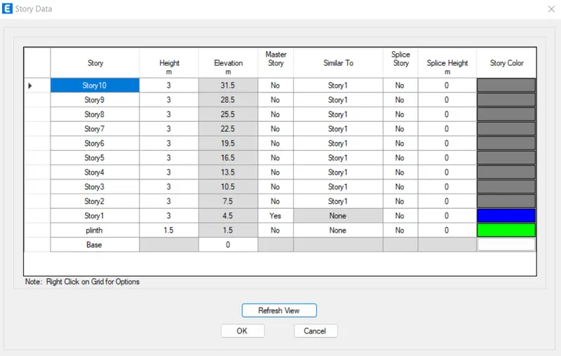
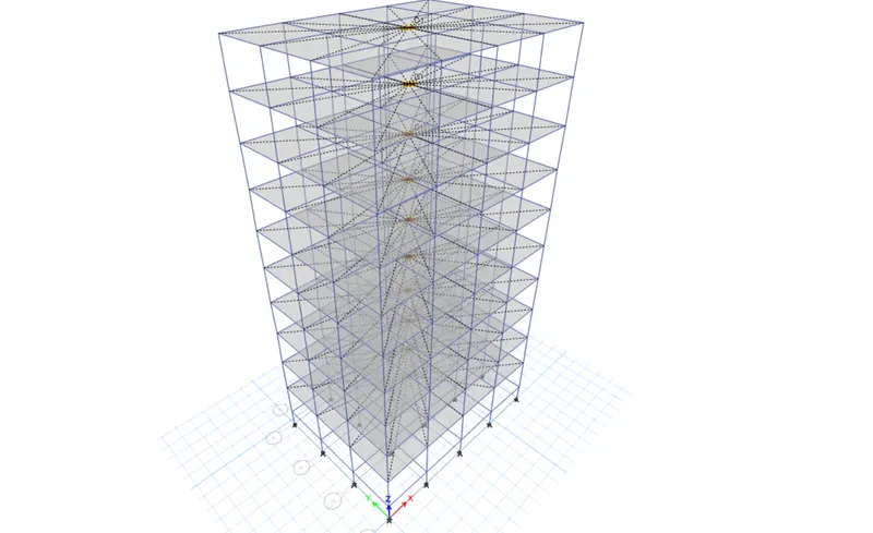
The difference between the Model D and Model E is that the Model E has 10 stories and differen column sections along the height.
- To add 5 more stories.
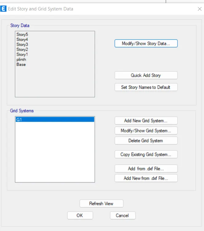
- Go to Edit tab under which choose option edit stories and grid systems ⮕modify show story data⮕assign the additional stories similar to story 1.
- To change the column properties along the height of the building.
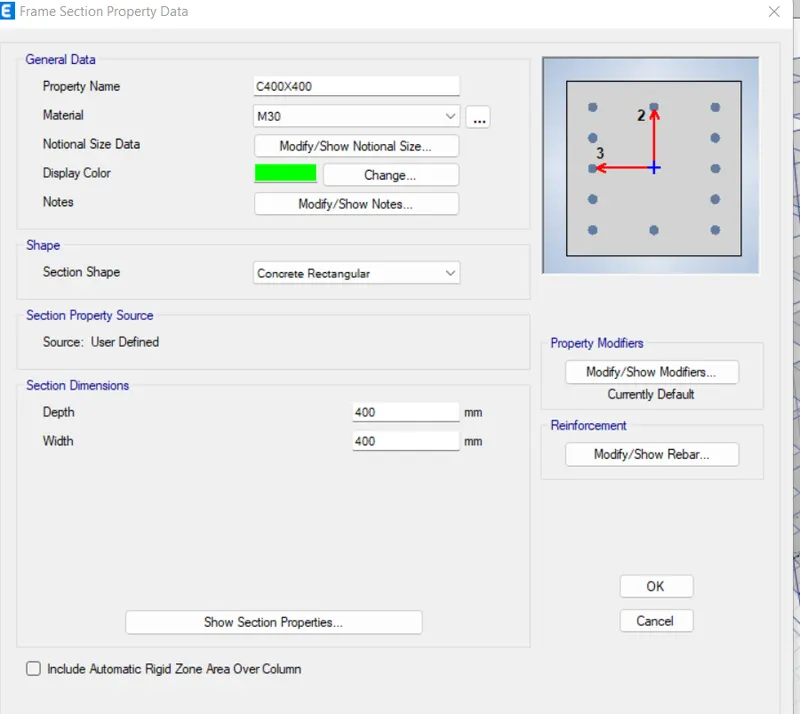
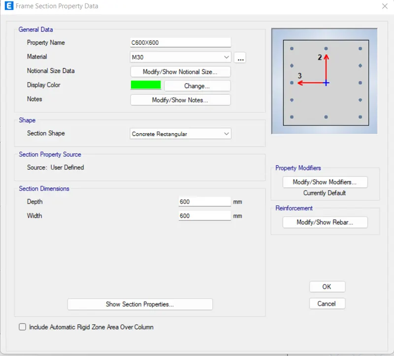
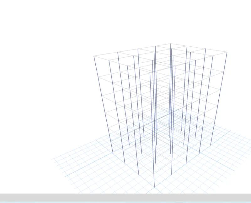
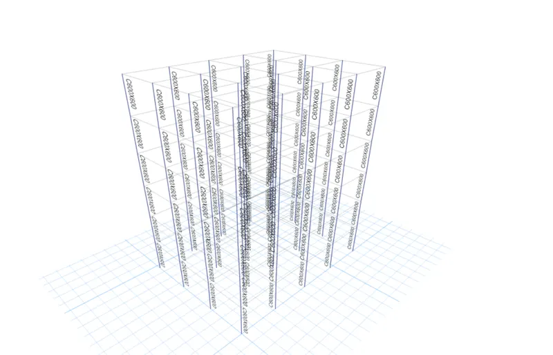
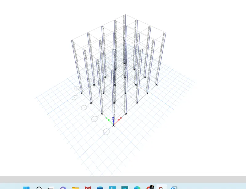
- In the upper five stories the column size is C400X400 while the bottom five stories have C600X600./
- First define both the columns in the section properties.
- To assign the C600X600 in the bottom five stories.
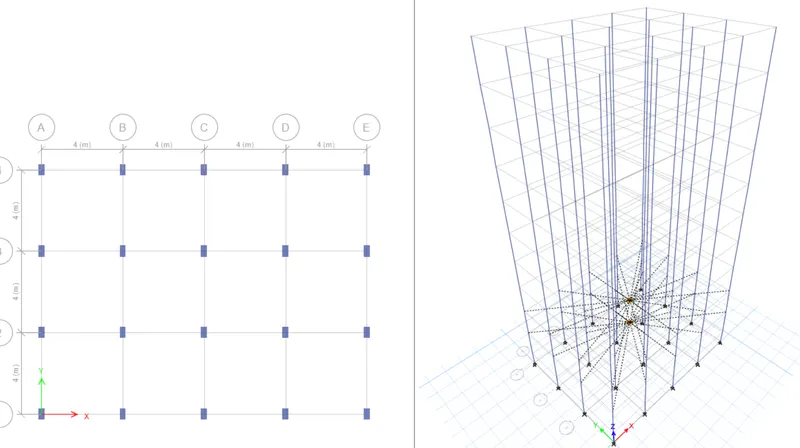
- Go to Set display option and uncheck the floors and beams so that only column is visible,then
- Go to view tab under which choose set building limits and under set story range select to view from story base to story 5.
- Select all the columns in 3D view then go to assign tab⮕frame⮕section property⮕apply to assign C400X400.
- Again,set the building view limit from story 6 to story 10 and assign the Column C600X600 to the selected frame.
- Reverse all the changes to view the full model and beams ,floors as well.
- Check for the Diaphragms in the model if it is there okay, otherwise provide it by seklecting the slabs.
- Run Analysis.
- Now save the model with save as option with the name as Model F for editing for model F itself.
6.Model F
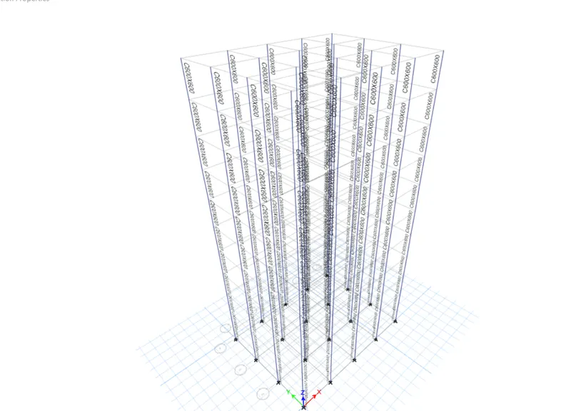
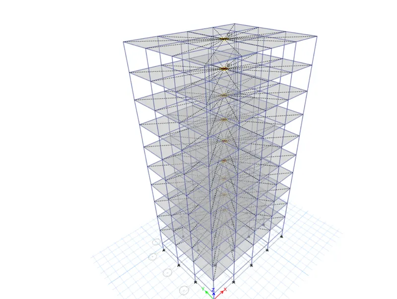
The difference between model E and F is that the model F has the same size of C600x600 column along the 10 story height of the building .
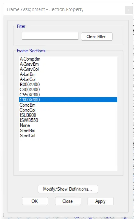
- To assign the C600X600 along the full height of the building.
- first set the display to view only column.
- then select all the joints and assign C600X600 column.
- Check for the Diaphragms in the model if it is there okay, otherwise provide it by selecting the slabs.
- Run Analysis.
- Now save the model with save as option with the name as Model F for editing for model F itself.
7.Model G
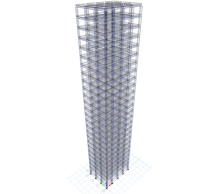
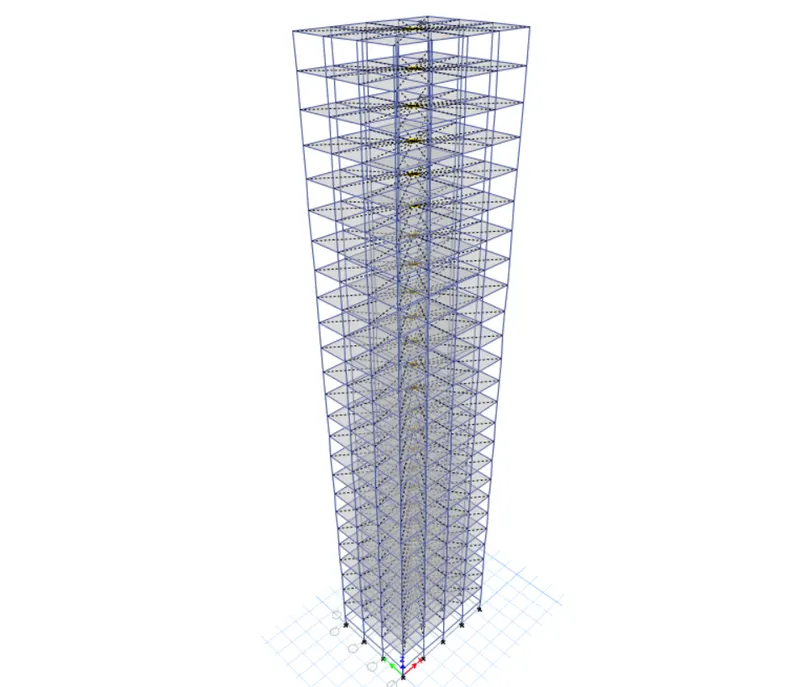
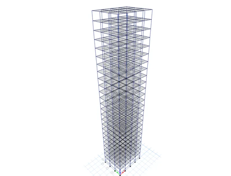
The model G has 25 stories and different column sizes along the height of the building.
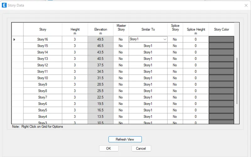
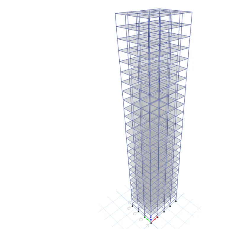
- Add stories into the model
- Go to edit under which choose edit story or grid system.
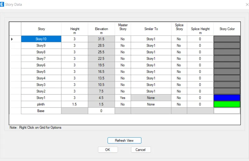
- Add 15 more stories into the model and make sure that all the added stories are set similar to story 1.
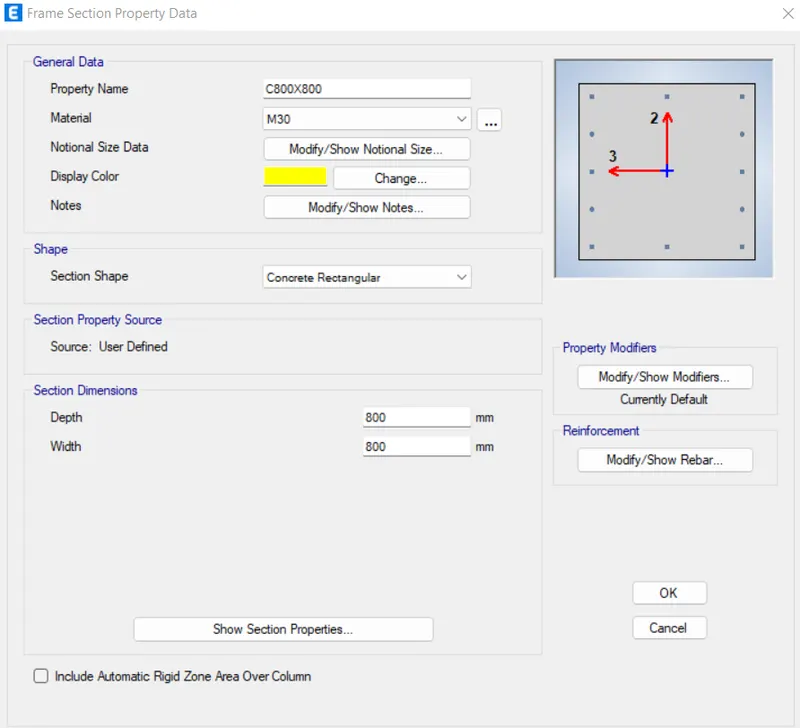
- Now, define the section properties as columns for different sizes.
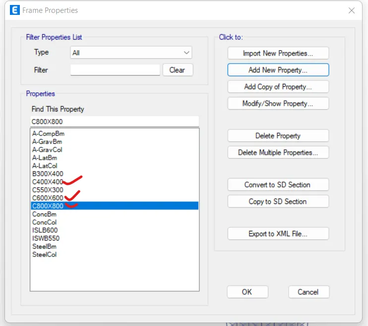
- Go to define⮕section properties ⮕frame sections.
- Define only one column size of C800X800 as C600X600 and C400X400 is already defined in the model.
- Now,Assign different column sizes along different height of the building.
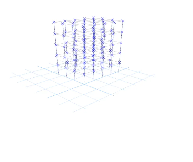
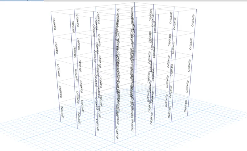
- First set the display to view only column vertical grids and beams and floors are made invisible.
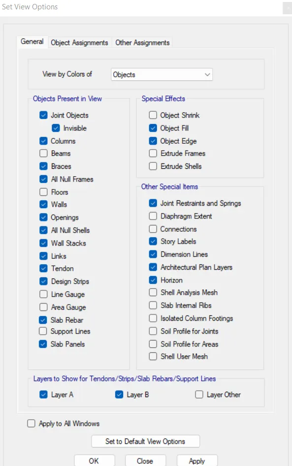
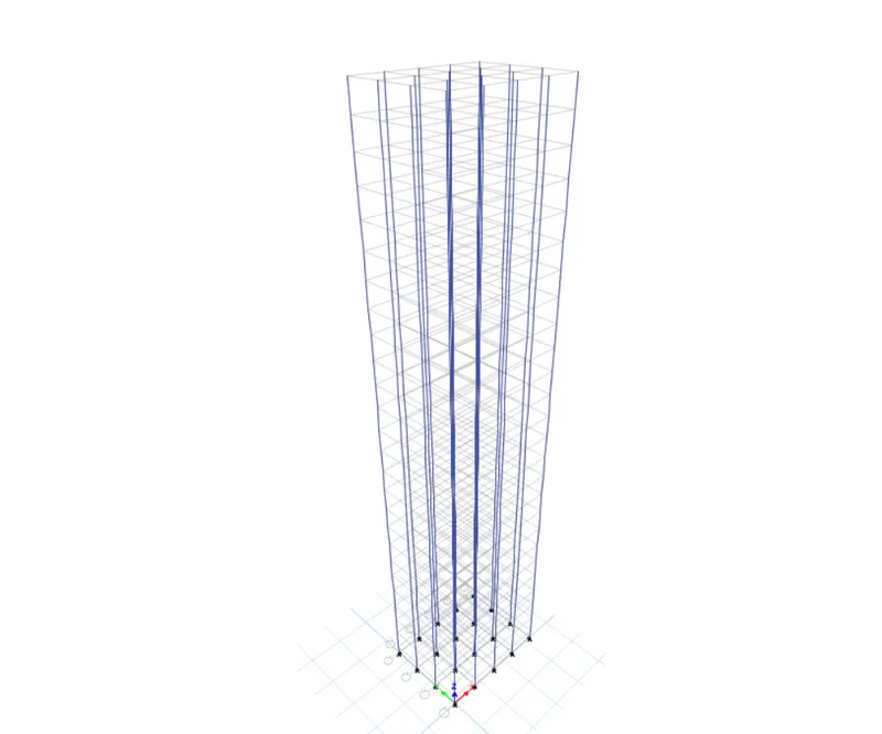
- then set the view from story base to story 10 to assign C800X800.
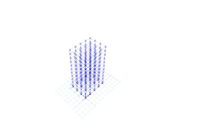
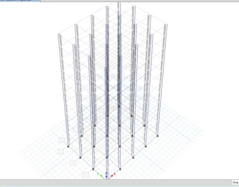
- then,again set the view from story11 to story 20 to assign C600X600.
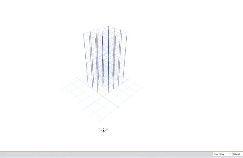
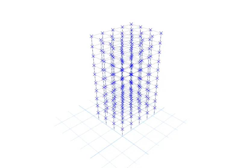
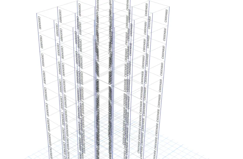
- then,again set the view from story21 to story 25 to assign C400X400.
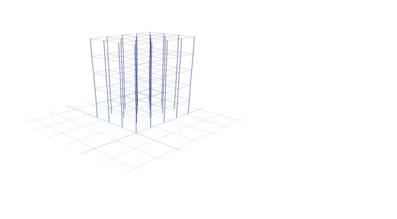
- Reverse the changes made to view the full model with beams and floors as well.
- Check for the Diaphragms in the model if it is there okay, otherwise provide it by selecting the slabs.
- Run Analysis.
- Now save the model with save as option with the name as Model F for editing for model F itself.
8.Model H
The difference between model G and H is that Model h has Column C800X800 along the total height of the frame.
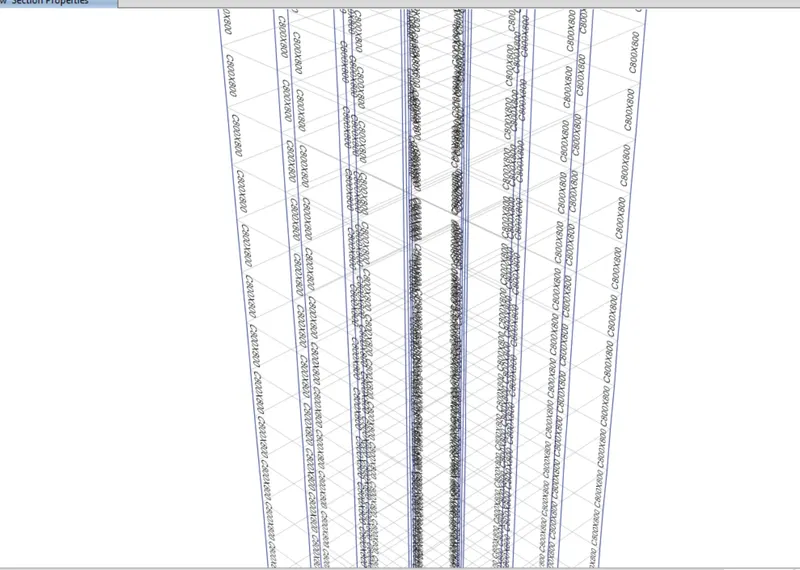
- To assign C800X800 along the full height of the frame,
- First set the display in such a way that only vertical grid lines is visible then,select the vertical grid lines.
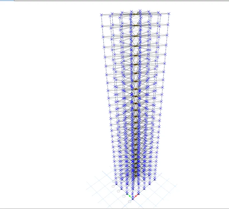
- Assign the Column C800X800 to the whole selected frame.
- Check for the Diaphragms in the model if it is there okay, otherwise provide it by selecting the slabs.
- Run Analysis.
- Now save the model with save as option with the name as Model J for editing for model J itself.
9.Model J
The difference between model H and J is that the live load has to be increased by 10% into the model.
- To change the uniform live load value into the model.
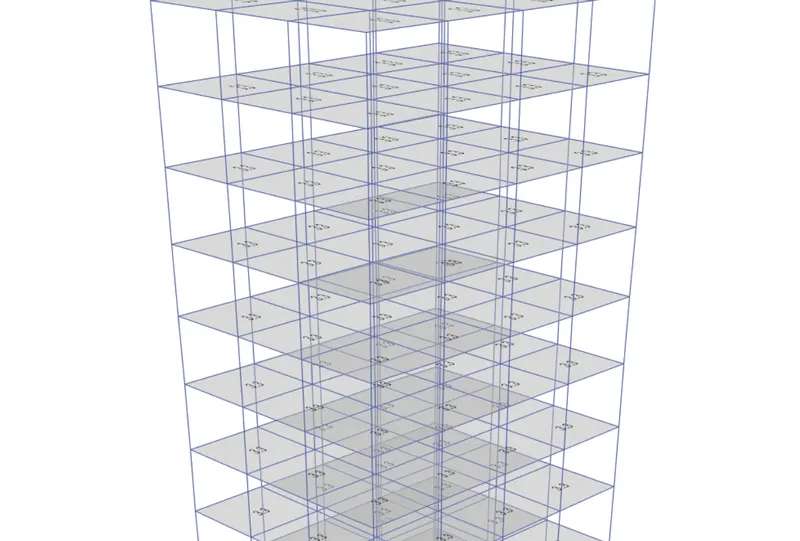
- First select all the slab shells from select tab.then,
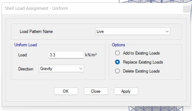
- Go to Assign tab under which choose shell loads⮕uniform⮕in the new opened tab change the uniform load value from 3 to 3.3 kn/m2.
- Make sure that under options replace existing loads is checked so that the loads get updated with a new value rather than adding with previous defined value.
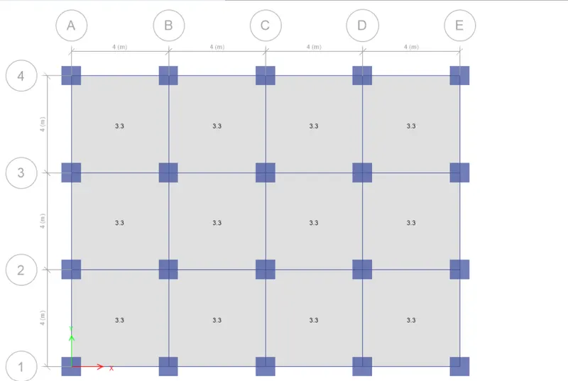
- Check for the Diaphragms in the model if it is there okay, otherwise provide it by selecting the slabs.
- Run Analysis.
- Now save the model with save as option with the name as Model K for editing for model K itself.
10.Model K
The only difference between model j and K is that model k has 10% increased uniform live load than model k.
- To change the uniform live load value into the model.
- First select all the slab shells from select tab,then
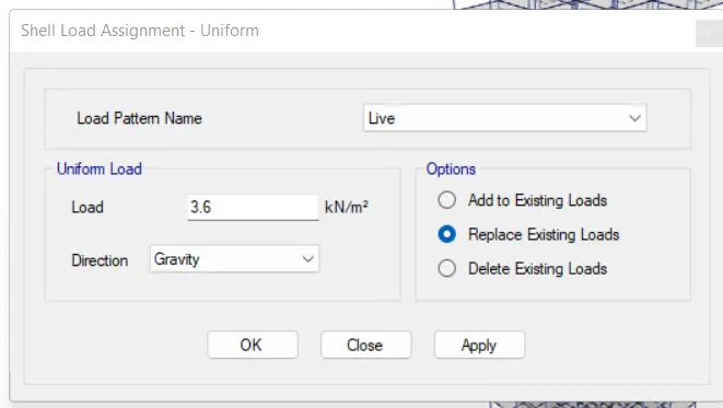
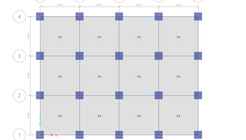
- Go to Assign tab under which choose shell loads⮕uniform⮕in the new opened tab change the uniform load value from 3.3 to 3.6 kn/m2.
- Make sure that under options replace existing loads is checked so that the loads get updated with a new value rather than adding with previous defined value.
The difference T
- Check for the Diaphragms in the model if it is there okay, otherwise provide it by selecting the slabs.
- Run Analysis.
- All the models are ready now for accessing the analysis results.
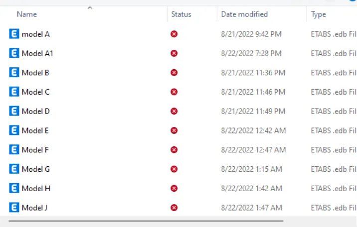
Results:-
- Comparative studies are tabulated as follows,and the conclusions are mentioned all along.
|
Criteria |
Model |
Analysis result |
Conclusion |
|
Effect of stiffness on time period
|
Building-E (with varying column size) |
1.208 s. |
As we can see with variable column sizes the time period is lesser than the uniform column sizes as in the frame of uniform column sizes the heavy masses are lumped at the top which increases the time period of the building considerably. |
|
Building-F (10 story with uniform column size) |
1.256 s. |
||
|
Building-G (25 story with varying column size) |
2.996 s. |
||
|
Building-H (25 story with uniform column size) |
3.372 s. |
|
Criteria |
Model |
Analysis result |
Conclusion |
|
Effect of mass on time period |
Building-H (25 story with uniform 3.0kN/m2 imposed load) |
3.372 s. |
As we can see that the time period is almost similar for all the three cases here, it is because the live load is provided uniformly all over the frame structure and also the uniform load value doesn’t have significant difference. |
|
Building-J (25 story with uniform 3.3kN/m2 imposed load) |
3.372 s. |
||
|
Building-K (25 story with uniform 3.6kN/m2 imposed load) |
3.372 s. |
|
Criteria |
Model |
Analysis result |
Conclusion |
|
Effect of building height on time period |
Building-A (2 story) |
0.34 s. |
It can be concluded with the results that, If the height increases definitely time period increases as the time period is directly proportional to the height of the building. |
|
Building-B (5 story) |
0.714 s. |
||
|
Building-F (10 story) |
1.256 s. |
||
|
Building-H (25 story) |
3.372 s. |
|
Criteria |
Model |
Analysis result |
Conclusion |
|
Effect of column orientation on time period |
Building-B (All floors column size C400X400) |
0.714 s. |
As we can see from the results of the time period in seconds for the uniform shaped column of building A has lower time period than C & D, while also the deflection of building D will be higher in X direction than Y and vice versa due to its orientation. |
|
Building-C (All floors column size C550X300 while oriented in X-direction. |
0.789 s. |
||
|
Building-D (All floors column size C300X550 while oriented in Y-direction. |
0.772 s. |
|
Criteria |
Model |
Case |
Analysis result |
Conclusion |
|
Effect of Flexural Stiffness of structural elements on mode shapes. |
Building-B |
Flexural stiffness of beams close to nil (Zero inertia) |
1.809 s. |
We can see that when we do not consider or considering the flexural stiffness of beams close to zero then the time period arrived is more than twice of the full flexural stiffness of the beams. |
|
Full Flexural stiffness of beams (regular) |
0.714 s. |
|
Criteria |
Model |
Case |
Analysis result |
Conclusion |
|
Effect of Axial Stiffness of vertical members on mode shapes. |
Building-H |
Axial cross section for columns is close to nil (Zero axial area) |
4.568 s. |
We can see that when we do not consider or considering the axial cross section for column close to zero then the time period arrived is more than that of the Full axial cross section for columns. |
|
Full axial cross section for columns (Regular) |
3.372 s. |
|
Criteria |
Model |
Case |
Analysis result |
Conclusion |
|
Effect of degree of fixity at column base on mode shape. |
Building-B |
Column support pinned (regular) |
1.809 s. |
We can see that the time period for fixed support is lesser than the pinned one so, it can be concluded that more the fixity lesser the time period. |
|
Column support Fixed. |
0.648 s. |