Modelling of 25 storey building with the specified properties using ETABS
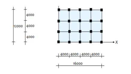
Model a 25 storey building on ETABS with structural properties as specified below. Ground floor or plinth floor level can be taken at a height of 1.5 metres from the base. Each of the successive 25 storeys has a storey height of 3 metres.
Structural Element Sizes
- Beams : 300 × 400 mm
- Columns : 800 × 800 mm
- Slab : 150 mm thick
Material Properties
- Grade of Concrete : M30
- Grade of Steel Reinforcement Bars : Fe 415
Loading
- Dead Load on beams from infill wall : 10 kN/m (Let us assume the same for roof floor in view of parapet)
- Live load on floor : 3 kN/m2 (Let us assume the same for roof floor)
a) Buildings are assumed to be pinned at the base
b) All columns in all storey are of the same size
c) All beams in all storeys are of the same size
d) Building is located on Soil type-II and in Zone-III. Assume other factors if required.
Aim:- To model a 25 storey building using Etabs for the given elements cross section.
Procedure:-
- Get open with the Etabs software.

- Go to file on the left top to create a new model in the etabs.
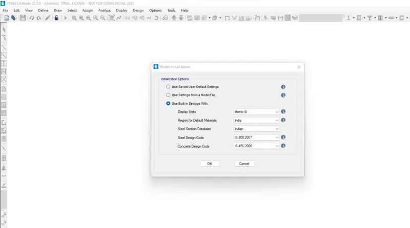
- A new dialouge box will get open with the name as model initialization⮕Mark the respective settings and tap ok.
- A new dialouge box will get open with the name as New model quick Templates⮕click custom grid spacing then go to edit grid data and define the grid spacing along X and Y directions of the plan.
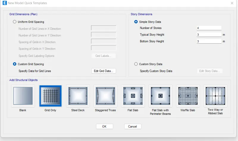
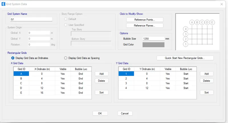
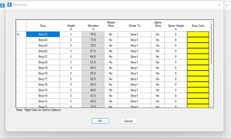
- Now, Select the custom story data then select edit story data and define the storeys from base to top 25th floor level.
- Specify the ground floor name as plinth and for all the above floors name it is from storey1 to storey 25 in such a way that storey 1 is similr to all other stories except plinth level.
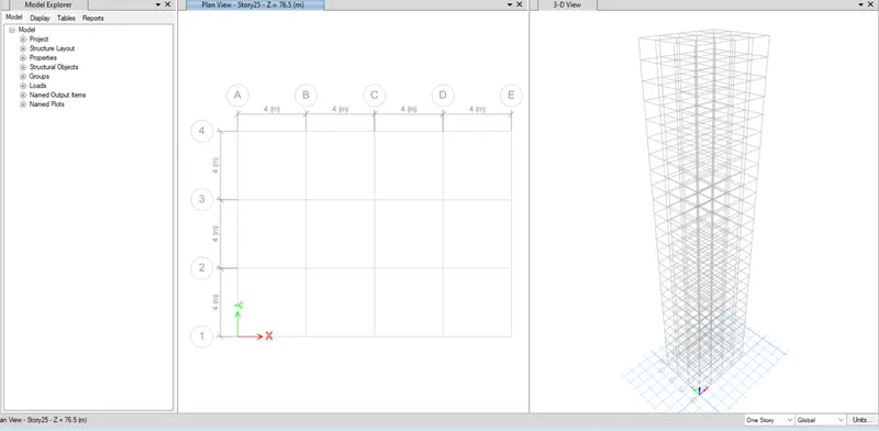
- The creates grid system model is replicated in the model space as follows.
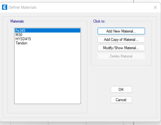
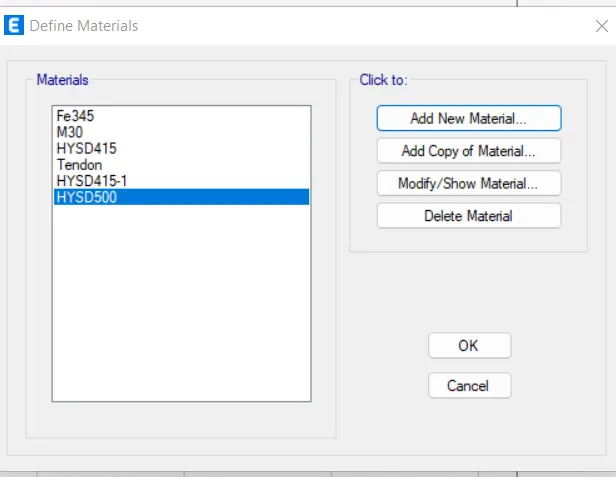
- Now, Go to define tab and choose material properties to assign the materials that will be the part of the model.
- Now, Go to define tab and choosing section properties frame sections to define the cross sections of beam and column.
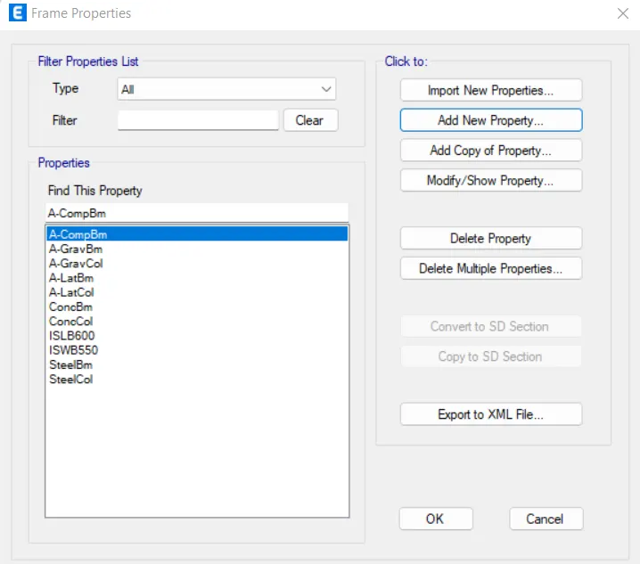
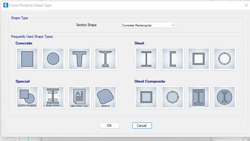
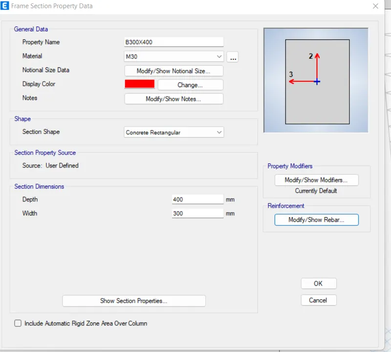
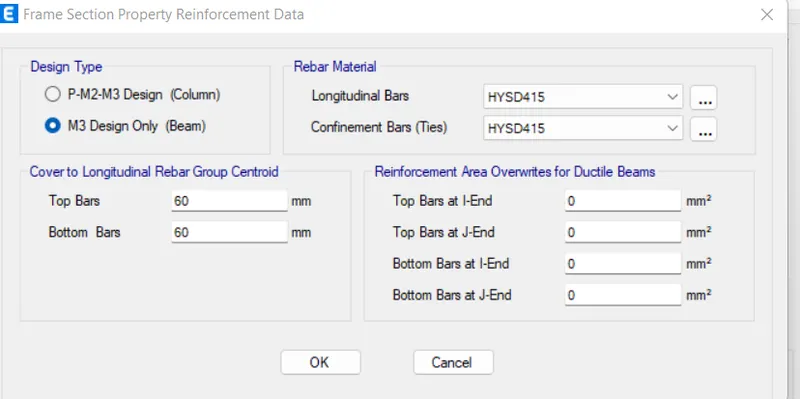
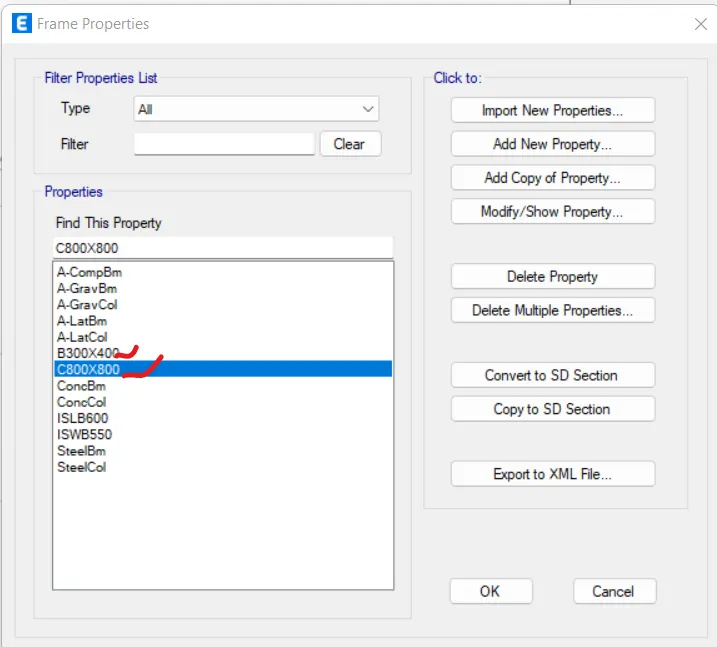
- Till the above the column and beam cross-sections and nmaterial properties are defined,now define the slabs.
- Now,Go to define tab and choose section properties under which select slab sections add new property for your desired slab specifications.
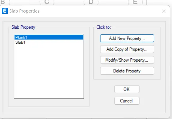
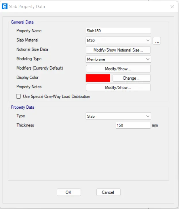
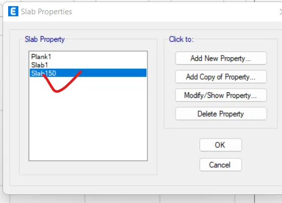
- Now,Define the load patterns,Go to define tab and select load patterns.
- Add the load types that are expected on the structure.
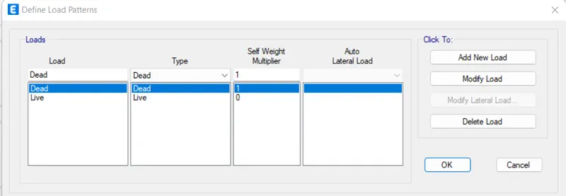
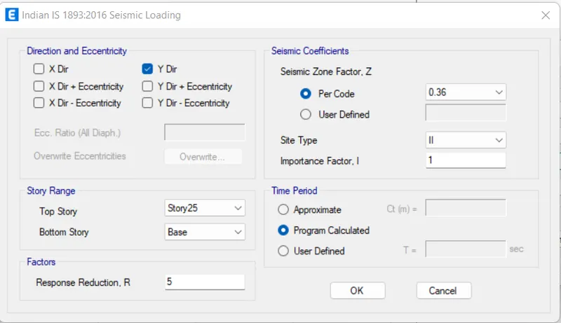
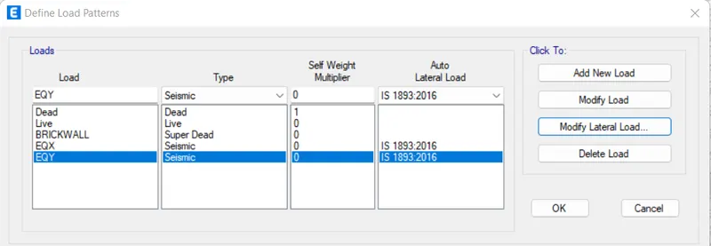
- Now, the next step could be defining the mass source.
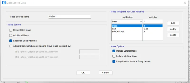
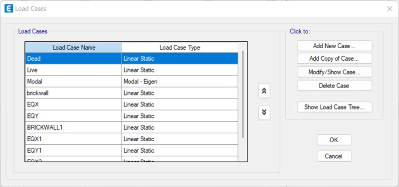
- Check for load cases after defining the probable load types.
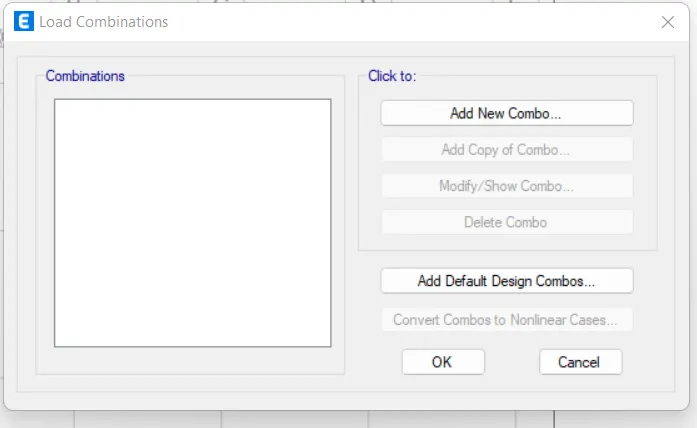
- Create the load combinations.
- Go to define tab under which choose load combinations.
- Default design load combinations will automatically get created here.
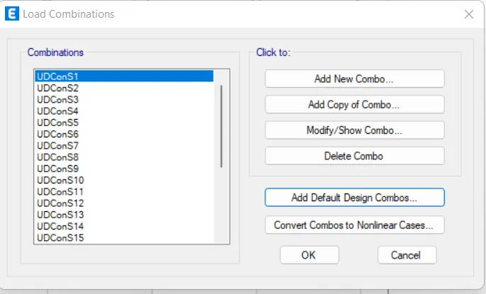
- Now,after the geometrical design,cross section selection,load cases and load combinations defined,the next step could be to assign them in the model.
- Go to quick draw columns option and choose the created column property from properties of object panel appeared just at the left of the model space.
- Before,Placing the columns to there desired location,first ensure that the all storey has been selected or not because the column has to go from base to top.
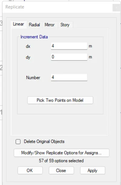
- Similarly select quick draw beams option and choose the created property from the left bottom and then assign the beams in one of the periphery of the grid and use replicate option to replicate the same all a way to the model.
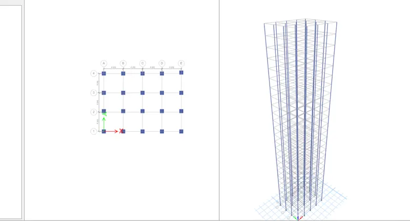
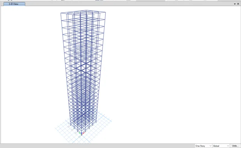
- Now,Assign the created slab into the model,for that first go to plan view of storey 1 then sellect similar stories so that assigning the slab membrane to storey 1 can be replicated to all other similar stories.
- Go to select the quick draw slab and choose the slab of 150 mm created from properties of object.

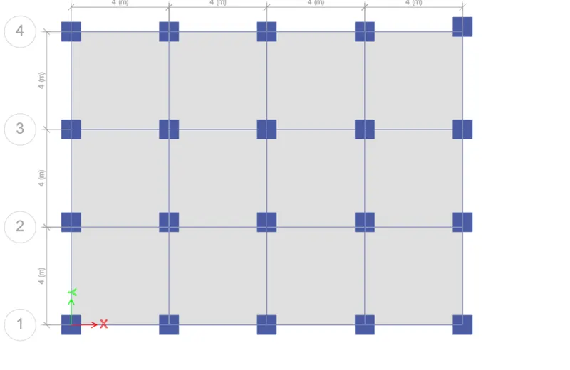
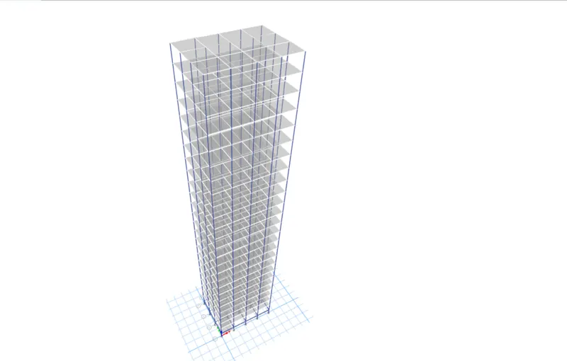
- Now,Assigning the loads into the model.
- Go to select tab and choose select option then property under which choose B300X400 property created to select beams.
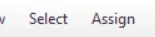
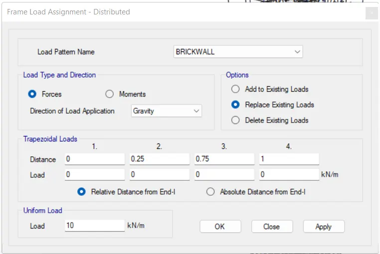
- Now,Go to Assign tab under which choose frame loads distributed.
- Select the load pattern name,then
- Provide the uniform load value then Dead Load on beams from infill wall : 10 kN/m as mentioned in the question.
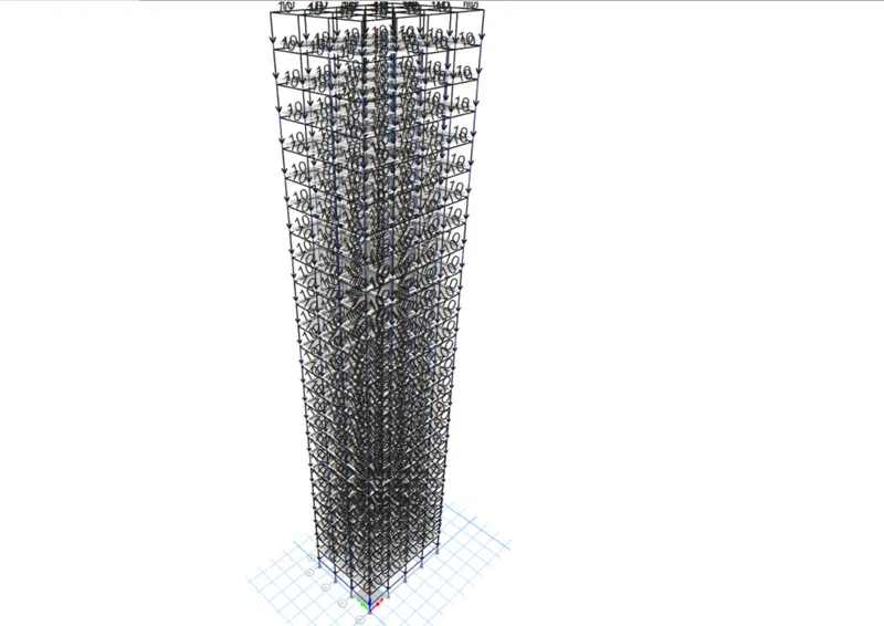
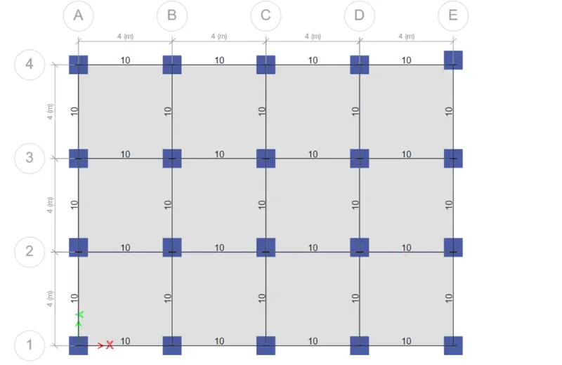
- Now using the select tab make selection of all the slabs to assign Live load on floor : 3 kN/m2 as mentioned in the question.
- Select ⮕properties⮕slab sections⮕choose the created property slab 150.
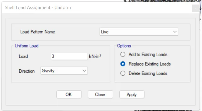
- Assign⮕Shell loads⮕uniform and feed the live load value as 3 kn/m2 as per directed in the question.
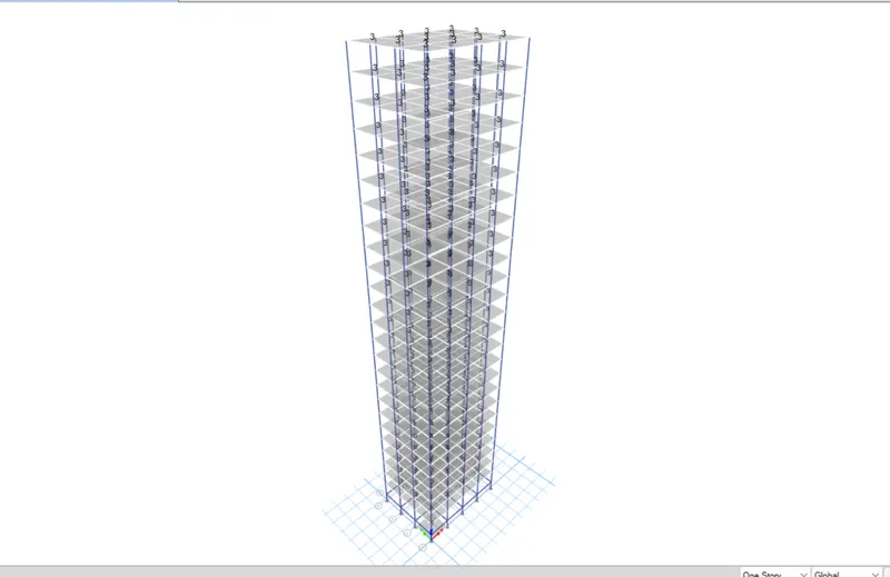
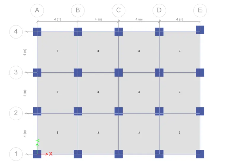
- Now, To assign the diaphragm property so that the centre of mass of the floor level shall automatically get created.
- Again select the slabs using select tab.
- then, Go to assign⮕shell⮕diaphragm⮕Chooose D1 ⮕apply⮕ok.
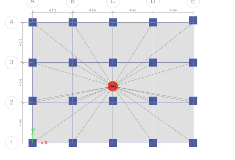
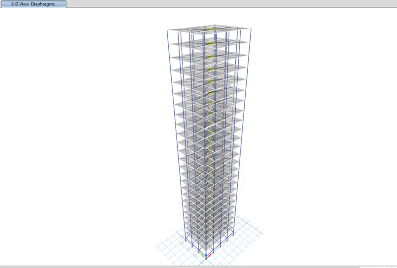
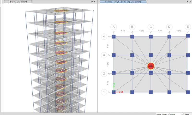
- Now,after completing the modelling part the next step is to Analyze the model.
- Wait for some time for completing the analysis part till the deflected shape of the floors get visible in 3D view.
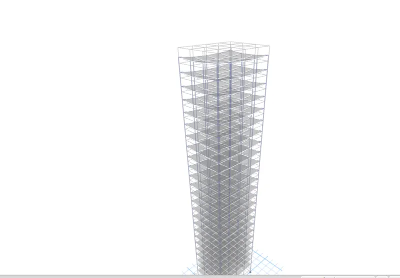
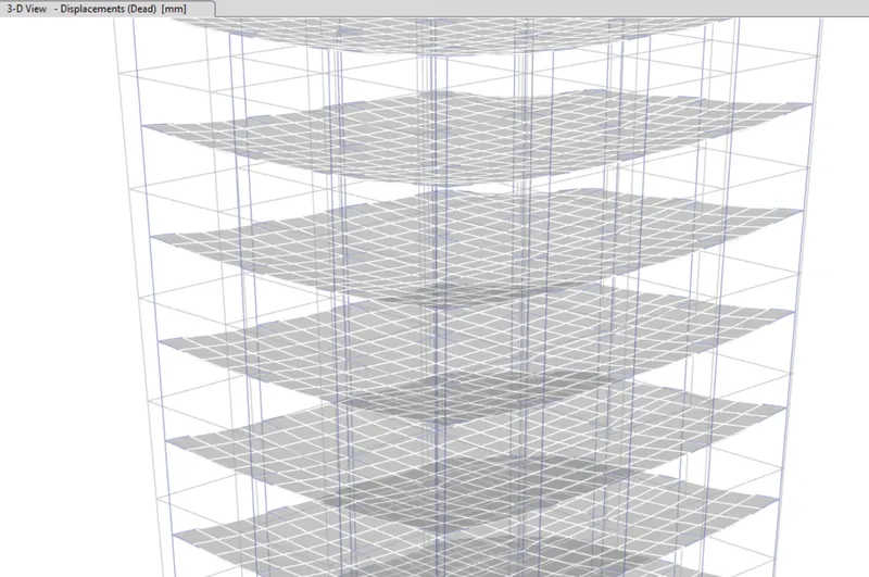
- Analysis Results Output:-
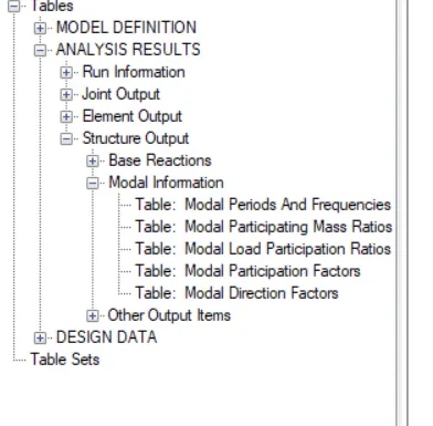
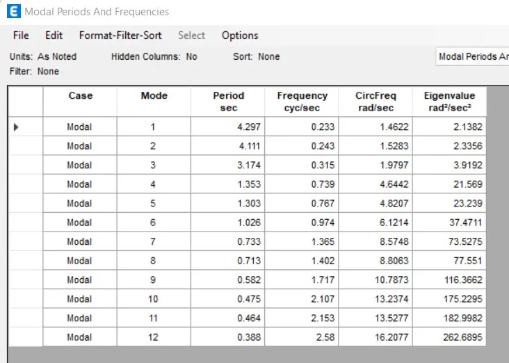
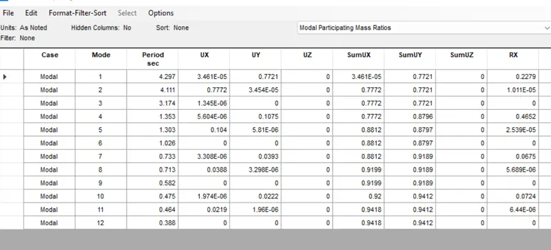
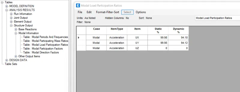
- Exercise Result:-
|
Criteria |
|
Desirable Solution |
Exercise Result |
|
Fundamental Translational natural period |
X-Direction |
4.4 Seconds |
4.297 |
|
Y-Direction |
4.2 Seconds |
4.111 |
|
|
Torsional Irregularity |
IS 1893-2016 (Part-1) Table-5. |
Torsional mode Time Period should be lesser than X and Y direction time periods. |
Yes |
|
Vertical Irregularity |
IS 1893-2016 (Part-1) Table-6 Clause-7. |
First three modes together should contribute at least 65% in mass participation factor in each principal direction. |
Yes |
|
Fundamental lateral natural periods in two principal plane directions are away from each other by at least 10% |
No |
||
|
Inter Story drift |
IS 1893:2016 (Part 1) Clause 7.11.1.1 |
Story drift shall not exceed 0.004 times the story height for base shear with no load factor (4x10⁻³) |
Yes |
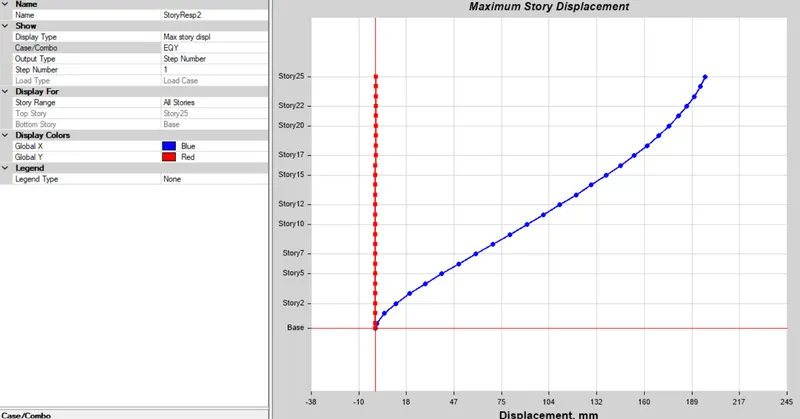
- Maximum Story Drifts due to EQX.
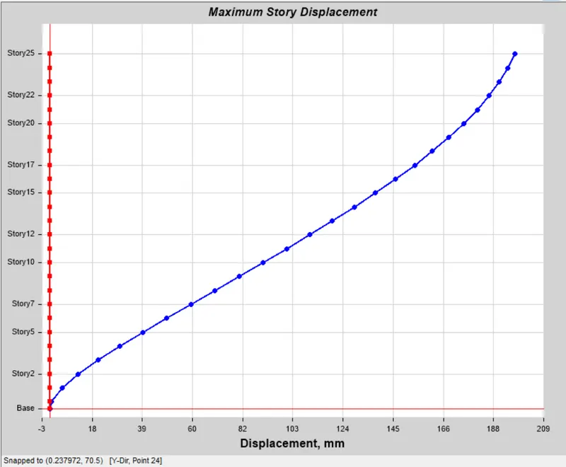
- Maximum story drifts due to EQY