Structural Modelling using Etabs 2018
Aim:- To model the structural frame using the given architectural plan in such a way that the model must comply with the provisions of IS 1893 and IS 13920.
Procedure:-
- Download the Architectural Auto Cad file given with the question
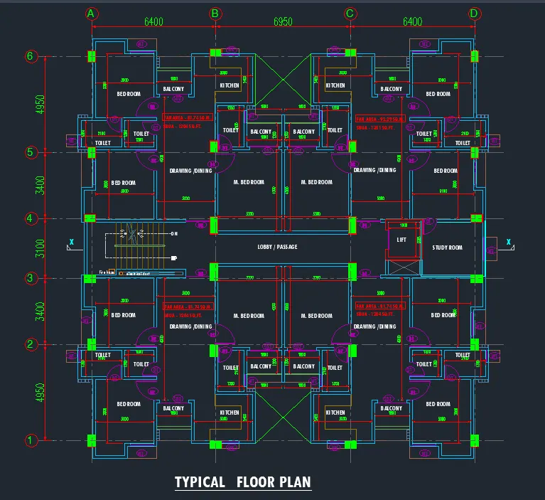
- Typical floor Plan
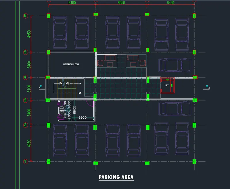
- Layout of the Parking Area
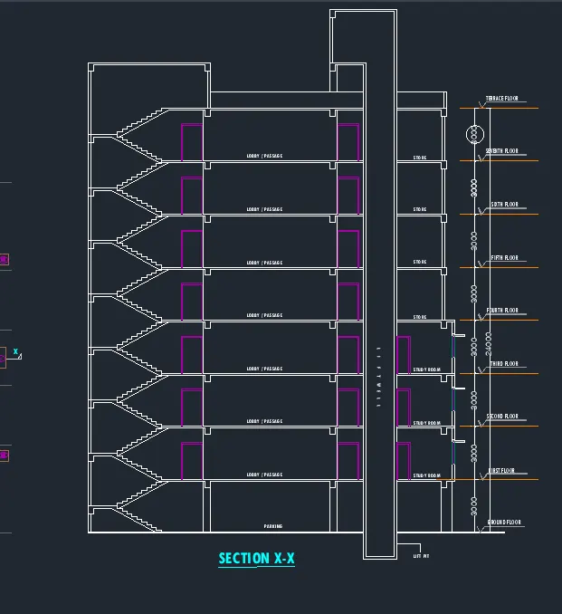
- Elevation of the layout-
- Get started with the Etabs for modelling the structural frame,
Before starting modelling in Etabs we should draw some keypoints from the architectural drawing, like as follows,
- Arrangement of the grid patterns
- Distance between the floor heights
- Undesrstanding of the architectural openings,
- provisions of the secondry beams.
- Selection of the location of the shear walls so that architectural openings should not get disturbed.
- Open the Etabs software,
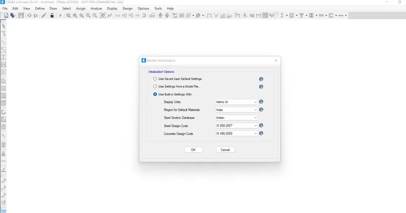
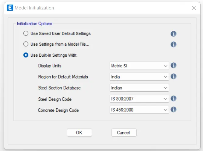
- In the model initialization tab to select use built in settings with,and markup the desireable seetings,
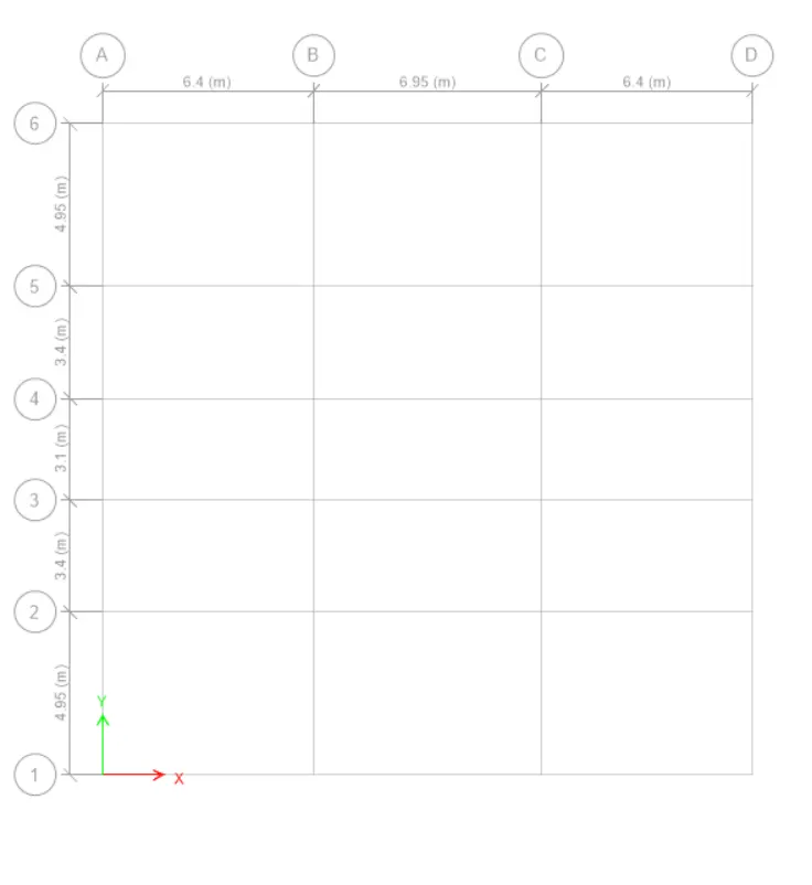
- In the new model quick template, select to choose custom grid spacing so that we can arrange our gridlines as per required by the architectural plan patterns.
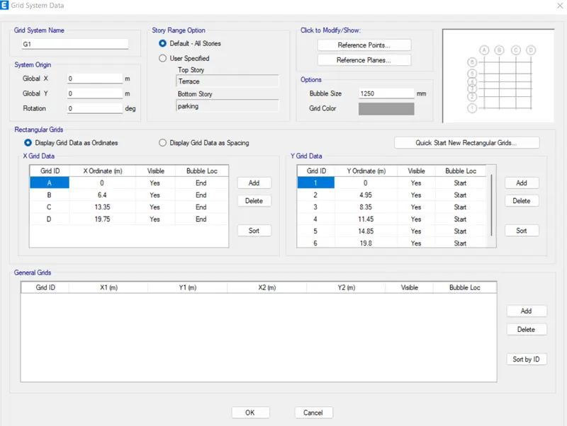
- By extracting the grid line data from the Architectural plan,the grid line arrangements are drawn as
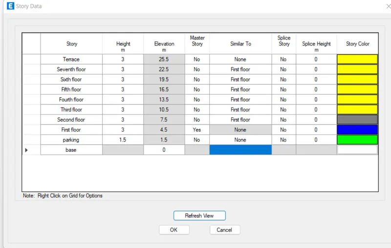
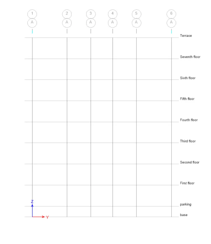
- Providing the story system in the model.
Before providing the elevation extract the elevation data from architectural plan elevation view plan and model it as follows,
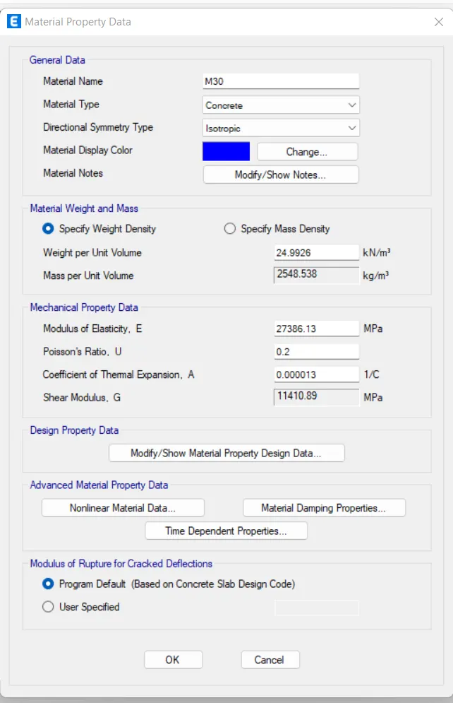
- Now, Define the Material properties,
- Go to define tab⮕under which choose Material Properties⮕Add new material⮕Choose the grade of concrete and the material will be added as follows
- Choose on more material as rebar for providing the grade of reinforcement in the system,
- Choose HYSD 415 for the longitudnal reinforcement while HYSD500 for shear reinforcement
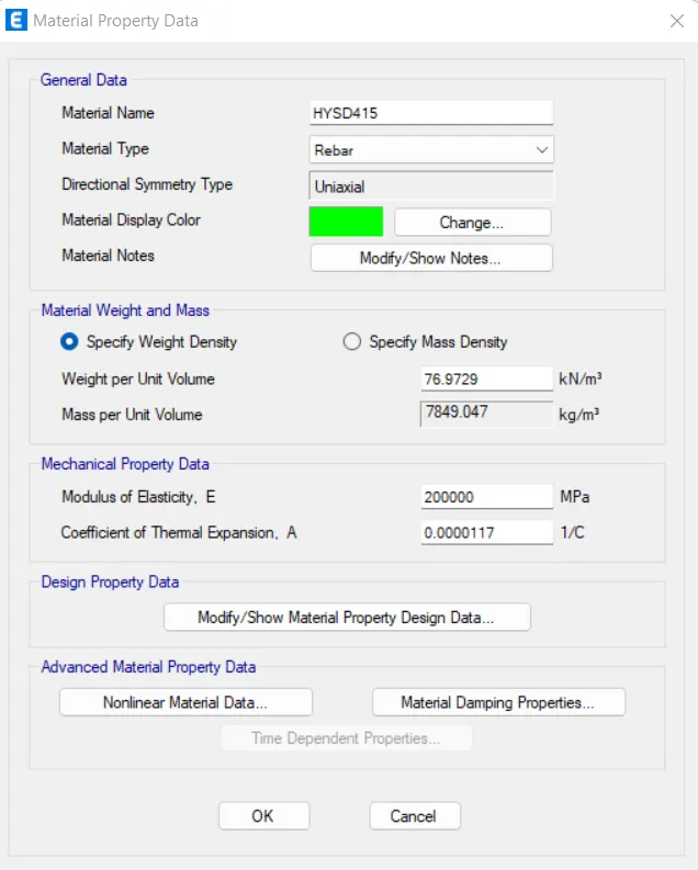
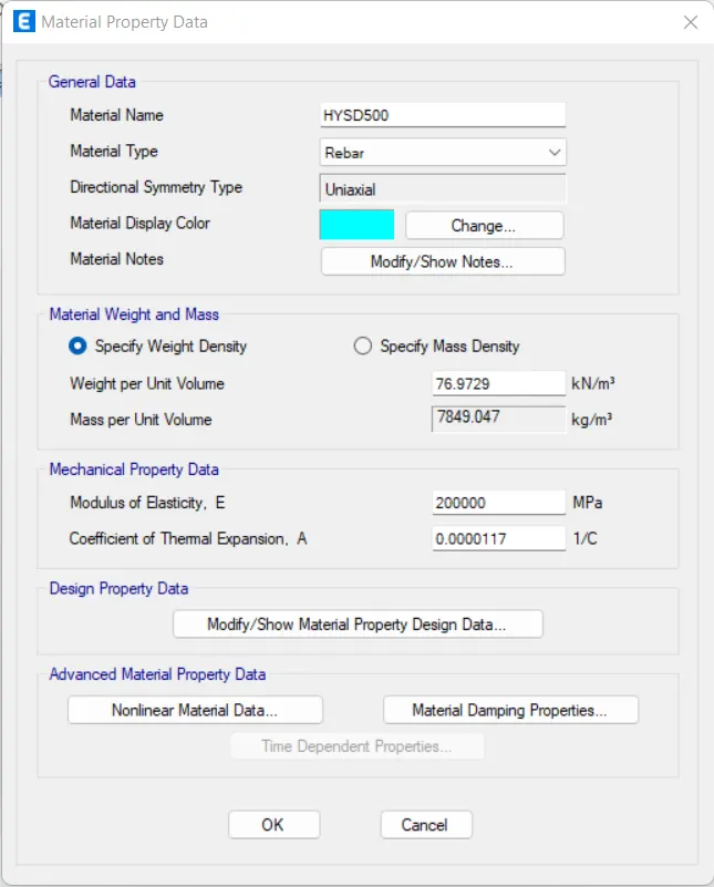
- Define the section properties of the model .
Go to Define tab⮕under which choose⮕section properties⮕frame sections⮕Add new property⮕define the beam and column sections
- As we know that we have to do modelling of the frame and analysis it on the trial basis so add more than one Beam sections that we can use it on trial basis feasibily,
Like B300X500,B550X350.
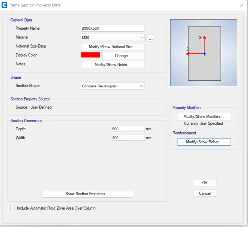
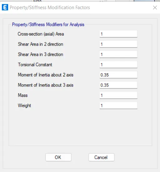
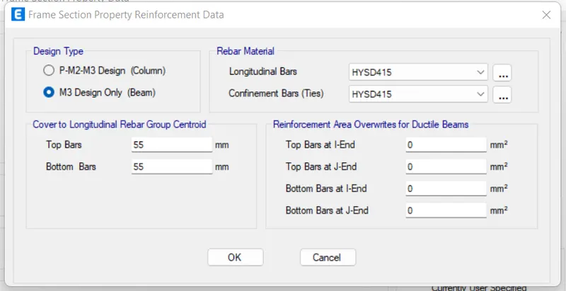
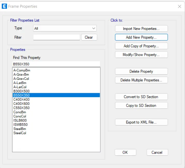
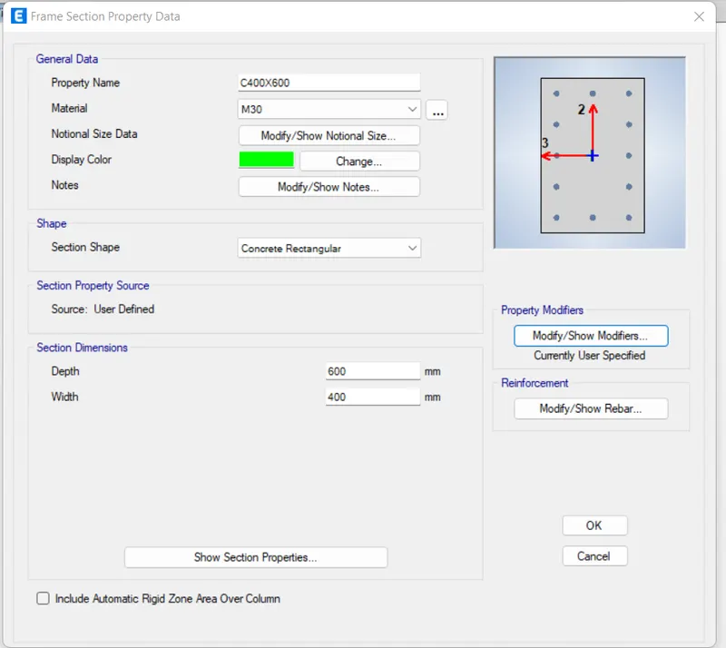
- Defining the C600X400,as follows
- As we know that we have to do modelling of the frame and analysis it on the trial basis so add more than one column sections that we can use it on trial basis feasibily,
Like C600X400,C400X400,C550X350.
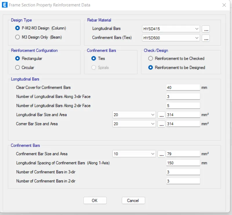
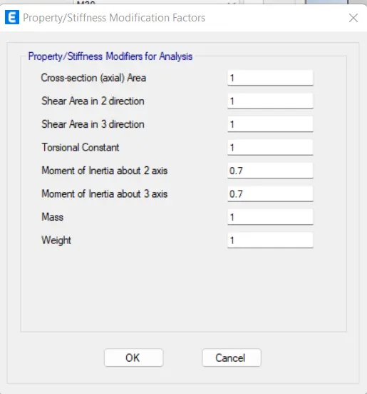
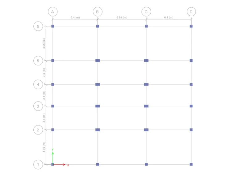
- Assigning the columns in the model in such a way that along the periphery provide C400X400 and in between provide C400X600 with the logic that along the periphery of the model the loads are lesser than than in the middle portion.
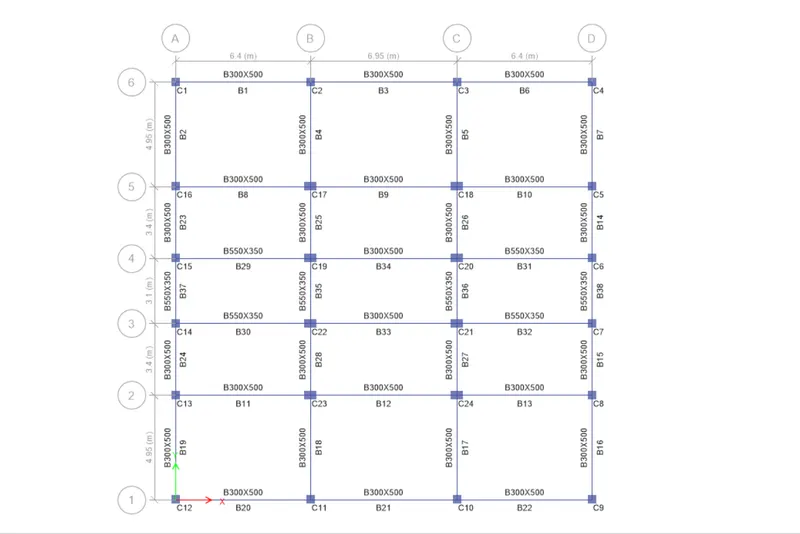
- Assigning the beams in the layout in such a way that B350X500 at the location where stair is placed while B300X500 on all other locations.
- Now, define the Slab members.
- Go to define tab under which choose⮕Section properties ⮕slab sections⮕Add new property.
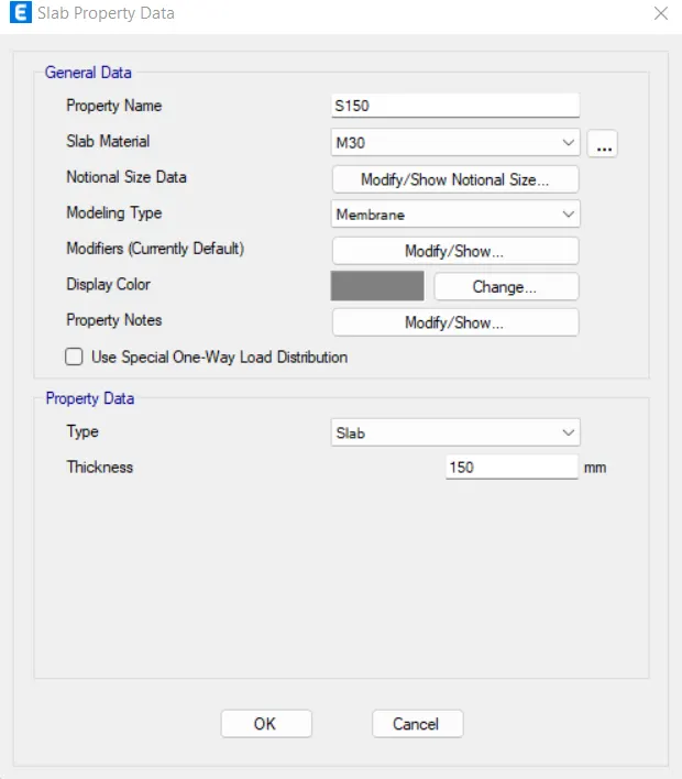
As we know that we have to do modelling of the frame and analysis it on the trial basis so add more than one slab sections that we can use it on trial basis feasibily,
Like S150,S125,S110...
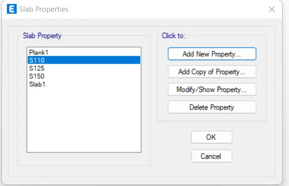
- Assigning the slab shells,
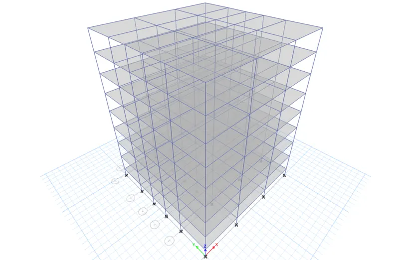
Now, Assigning the secondry beams which comes into the frame due to the partition walls.
- Now,define load Patterns
Go to define tab under which choose Load patterns then add the desired load patterns.
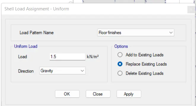
- It is a good practice to add the gravity loads like dead,live,frame,floor finishes loads first and also assign them to the model then only go to define earthquake loads so,
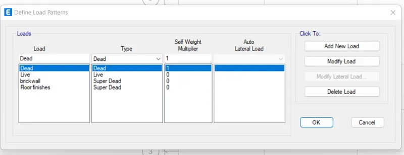
- Calculation of the Brickwall loads
Assume thickness of the wall=250 mm
Ht of the wall =3 m
Density of AAc block=6kn/m^3
Thickness of plastering both sides assumed to be=25mm
Density of plastering
Brickwall load = load imparted by the brickwork+load imparted by both sides plastering
Calculation of the Brickwall loads=height of wall X thickness of wall X density of AAC block+=3X0.25X6+0.025X3=6KN/m
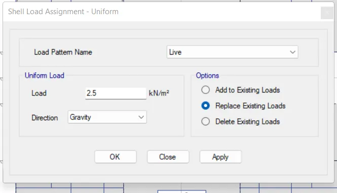
Extracting the live load values from IS 875-part (2)
For a Residential building the code of practice for live load are as follows,
All rooms And Kitchen=2 Kn/m^2
Toilet and Bathrooms=2 Kn/m^2
Corridoor,passsages,Stircase,store rooms,Balconies=32 Kn/m^2
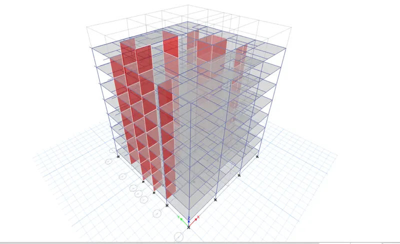
- The Structural model with the secondry beams and shear walls are assigned, as follows
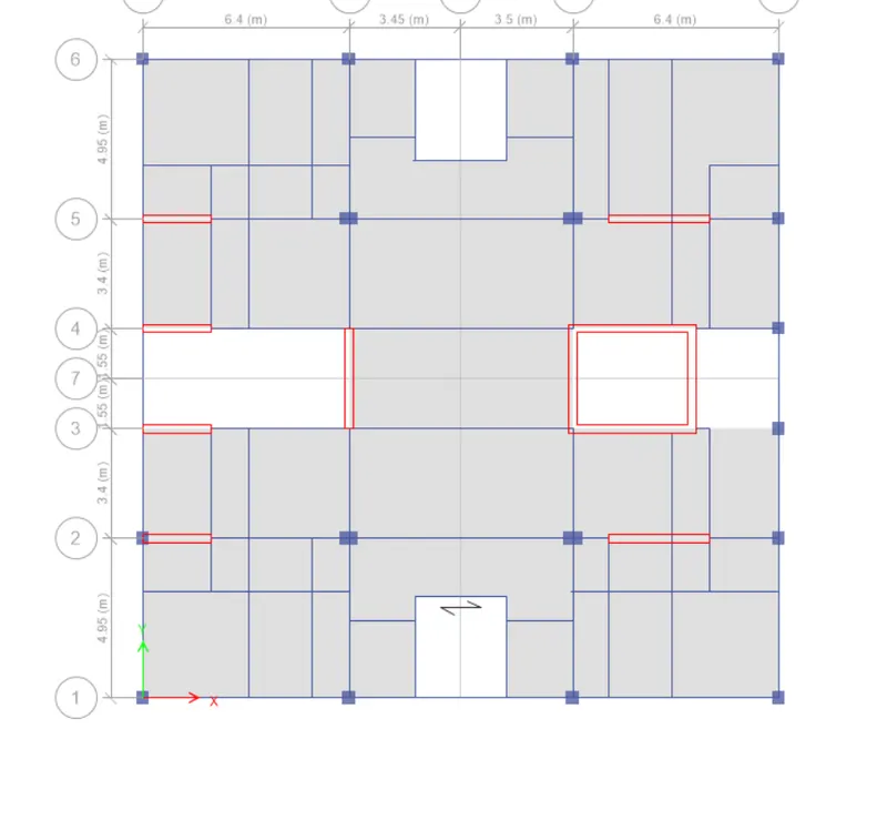
Now,Assigning the loads to the model,
- Assigning the frame loads,
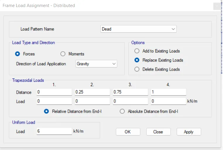
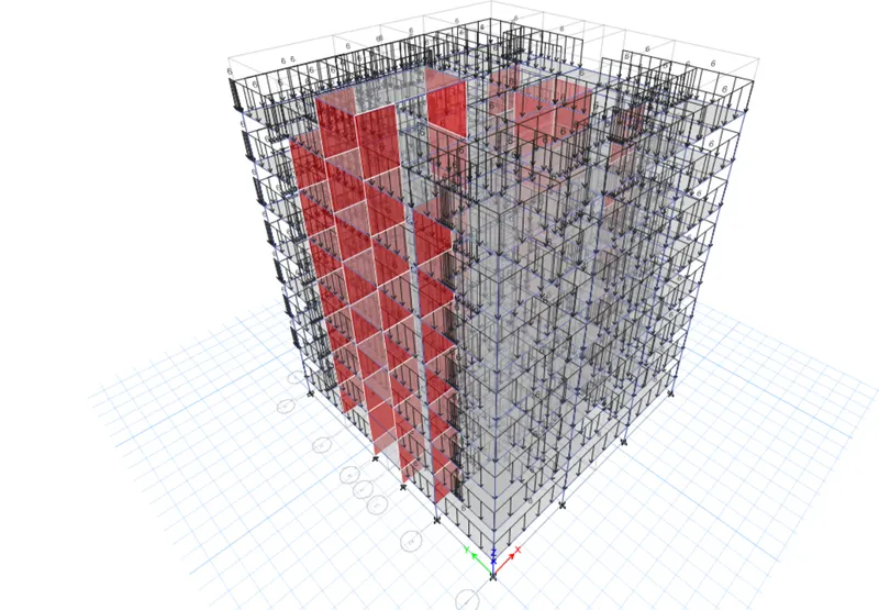
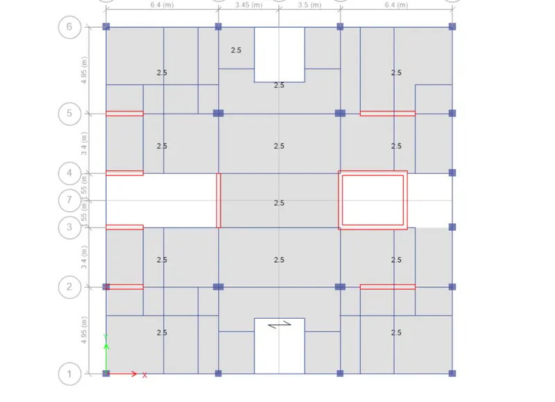
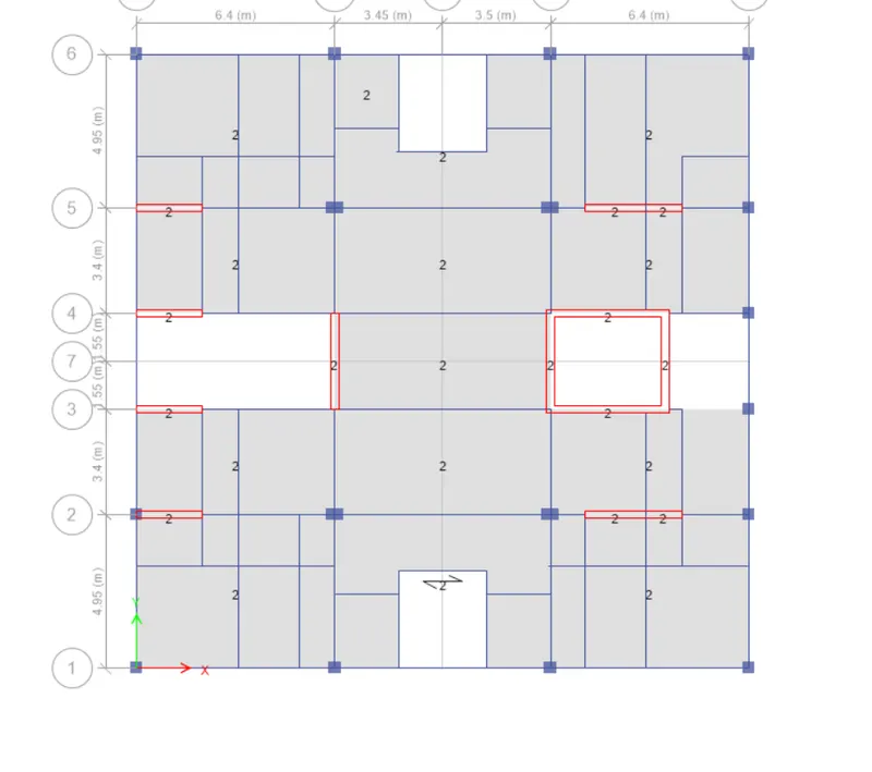
- Assigning the live loads,
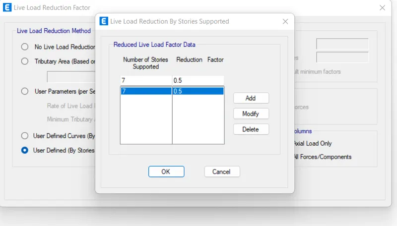
- Include live load reduction factor,
- Model Analysis Spectrum-
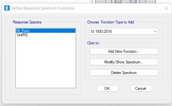
- Go to Define under which choose functions then select Response spectrum.
- A new tab will open under which define your Code of practice as IS 1893-2016.
- Now, Go for adding new function,Give your desired function name
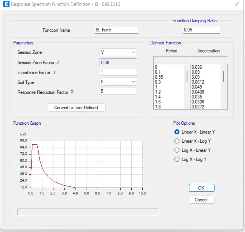
- So, the Response spectrum function has been defined,
- Now, Go to load cases and add the new load case to define the response spectrum model
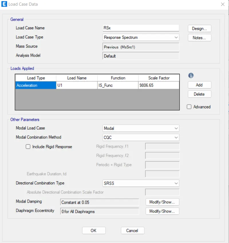
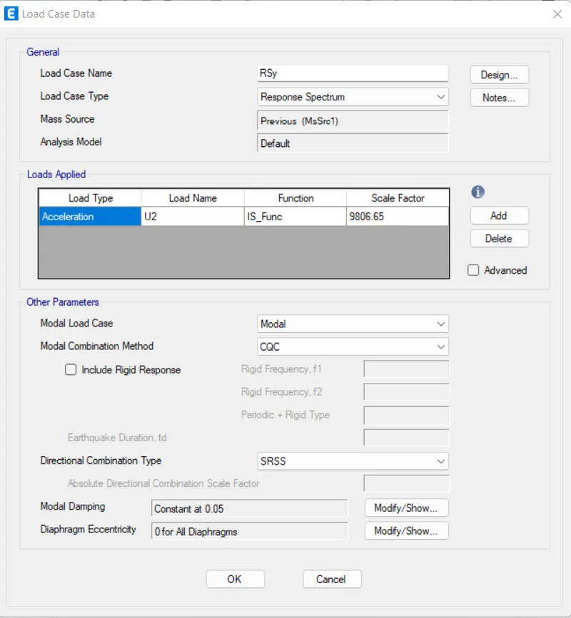
- Now,Go to load combinations to include the response spectrum model load cases as follows,
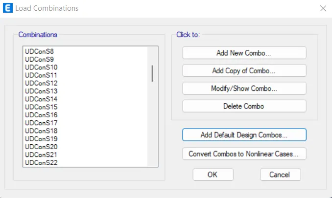
- Now, The model is set to Perform the analysis,
- For the analysis of the model use play button available in the tool palletes and wait till the deflected shape of the model arrives.
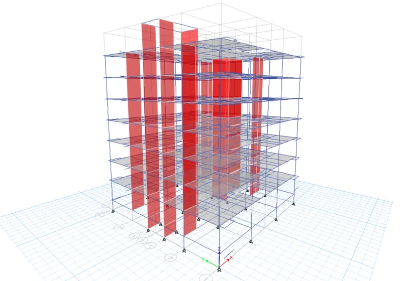
- Results:-
- Base reactions Table
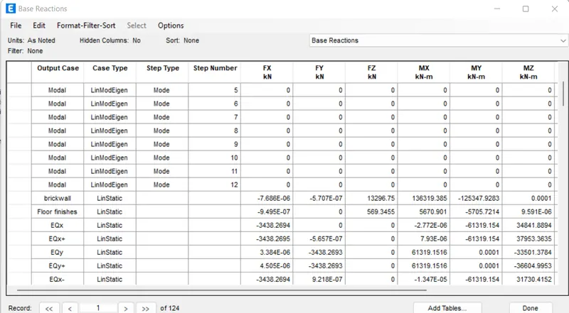
- Modal mass participation ratio,
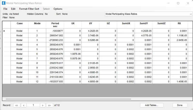
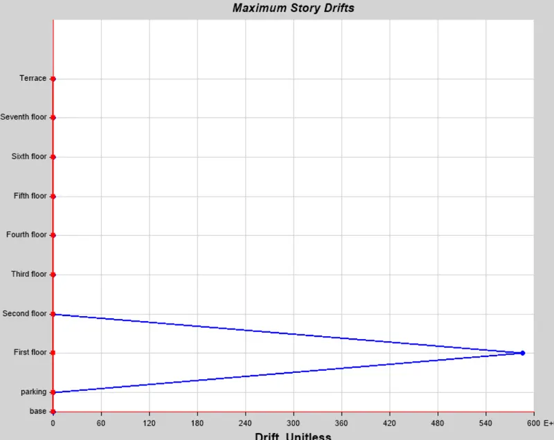
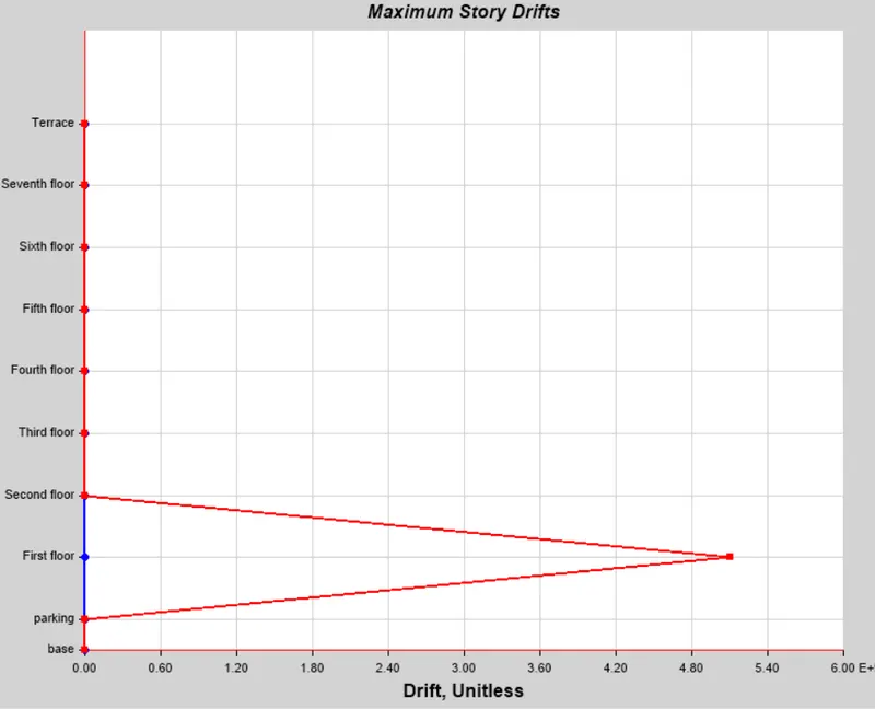
- Inter storey drifts,