Conceptual design of a building with columns and shear walls
Question 1:
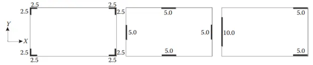
The building shown, 20 × 35 m in plan, has columns on a 5 × 5 m grid and shear walls (with dimensions shown in m, 250 mm in thickness) in three alternative arrangements, (a), (b), (c), all with the same total cross-sectional area of the shear walls. Compare the three alternatives, taking into account the restraint of floor shrinkage, the lateral stiffness and the torsional one with respect to the vertical axis, the vertical reinforcement required for the same total flexural capacity at the base, the static eccentricity, the system’s redundancy, foundation systems, architectural constraints etc.
Answer,
- Restraint of floor shrinkage
Observations,
As we can see from the given size of the plan layouts the plan A has the shear walls at all there four corners and the plan B has shear walls in the centre orthogonally at all the four sides while plan C has two shear walls at the corners on right side extended to longer sides and one on left side extended to shorter side of the plan.
Conclusive statement on the alternatives,
Plan A Will serve the best in restraining the floor shrinkage as it restraints the floor from all the four corners and all the shear walls are symmetrical and orthogonal to each other and extended equally on all four corners, Plan B can also be marked as ideal situation for restraining the floor shrinkage from all the four sides but Plan C won't serve good for restraining the floor shrinkage as it is not symmetrical from all the sides,on some sides it extended complete wall while on the other side it completely leftover.
- Lateral stiffness
Observations,
As we can see in the plan A due to cornering of the shear walls the lateral stiffness decreases ,but in Plan B the shear walls are very well distributed along the periphery which will imparts greater stiffness to the structure.
Conclusive statement on the alternatives,
Plan B will serve the best in terms of stiffness as the shear walls are very well distributed uniformly along the periphery of the plan.On the other hand Plan A and C has non-uniformly distributed shear walls along the periphery of the plan.
- Torsion with respect to vertical axis.
Observations,
As we can see from the plan A the shear walls are uniformly distributed along the corners and in Plan B also shear walls are regularly placed while in plan C shear walls are non uniform and irregular.
Conclusive statement on the alternatives,
The kind of distribution of walls in Plan A and B will serve good in terms of torsion with respect to vertical axis,on the other hand plan C will serve poorly in terms of torsion with respect to vertical axis as the shear walls provided in plan C is non- uniform and irregularly distributed.
- Vertical Reinforcement for similar base capacity.
Observations,
As observed by looking into the plan,the plan A is subjected to nominal flexural moment and heavy twisting moment and for plan B it can be said that the walls are subjected to nominal twisting moment while ,plan C depicts that the walls are subjected to heavy flexural moment and twisting moment.
Conclusive statement on the alternatives,
The plan C shear walls will required higher volume of vertical reiforcement while the plan A and B will be requiring the least volume of reinforcement.
- Static Eccentricty
Observations,
By looking into all the three plans we can say that Plan A and B is Structurally symmetric while plan C is clearly structurally unsymmetric.
Conclusive statement on the alternatives,
As the plan C is structurally unsymmetric in that way it will create significant eccentricity in the structure.
- System's Redundancy
Observations,
By looking into the plans we can say that plan A and B will support lateral loads in both the major directions and Plan C will support lateral loads in both the major directions.
Conclusive statement on the alternatives,
The kind of uniform distribution of walls in Plan A and B will serve good in terms of redundancy while plan C is poor in terms of systems redundancy.
- Foundation Systems.
Observations,
In Plan A,due to the L shaped walls fixing the geometry and designing the foundation system will be a difficult taskbut, for plan B we can say that as the walls are in line and well distributed along the periphery the geometry and designing of the foundation system will be easy while in plan C we can see that the walls are in line but due to walls irregularity its designing will be a very difficult task.
Conclusive statement on the alternatives,
Plan B and C can be incorporated with isolated and strip footing type of foundation while for plan A it is recommended to have peripheral box type foundation system.
- Architectural constraints
Observations,
By looking into the plans we can say that in plan A as it is on all the corners so the distribution of the architectural elements can be symmetrically done and for plan B as it is in the centre of the periphery of the plan it will disturb various architectural constraints as the opening cant be made there but as in A architectural elements can be uniformly distributed in plan B while in plan C wide wall is along the shorter side of the periphery which will disturb the openings on the side and will not allow passage from one side to the another straight side.
Conclusive statement on the alternatives,
Architecturally speaking, plan A is most suitable while Plan B and C is a subject of discussion, additionally for plan C we can say that it cant be accepted either for residential or commercial as it is a complete failure plan on architectural grounds.
Question 2:
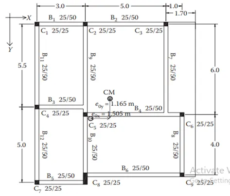
Discuss the suitability for earthquake resistance of the moment resisting framing plan of a three-storey building depicted here (cross-sectional dimensions in cm), the eccentricity of the centre of mass (as centroid of floor plan) to the centre of stiffness (from the moments of inertia of the columns) are shown. Suggest an alternative. Also, is there torsional flexibility? Are the two fundamental translational modes of vibration larger than the fundamental torsional mode of vibration. Discuss qualitatively.
Answer,
There are several issues which should be pointed out of the given Moment resisting frame above,the issues are listed and explained as foloows.
- Indirect lateral load transfer in X and Y directions-
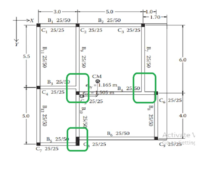
- As we can see in the given plan layout there are certain beams which are starting from one end but terminated in between, and this case is along both the major directions which causes the discontinuity in the transference of the inertial forces from one end to the other end. One more thing here is,the ideal situation is that the beams should be arranged in such a way that it should rests on the column on there both ends but, here the beam starting from the left side got connected with another transverse direction beam in such conditions, the beams may be subjected to shear failure.
- Structural eccentricity-
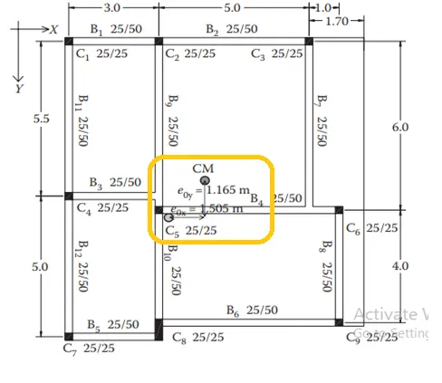
Here, we can clearly see that the eccentricities are along X and Y both the directions and as we know that if the distance between the centre of mass and centre of stiffness ig larger it creates a larger eccentricity between them which causes the weaker frame against torsion and the structure becomes torsionally flexible in both X and Y direction.
- Strong beam weak column possibility.
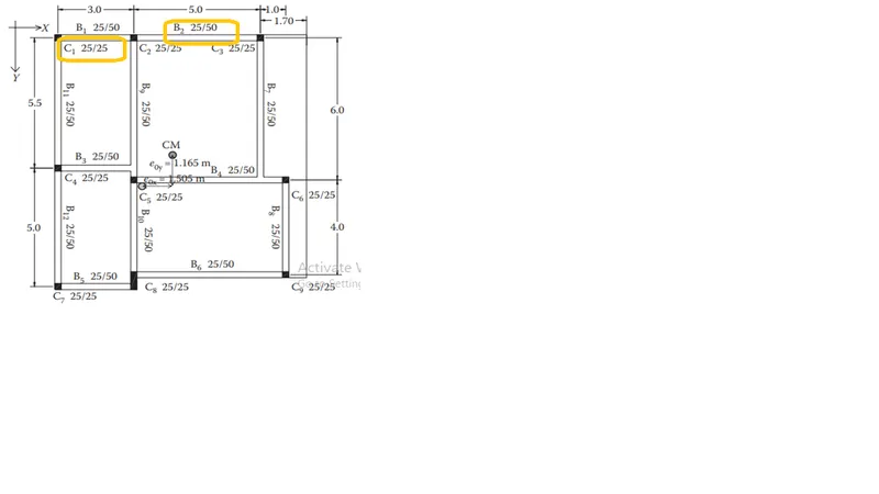
This situation arises here because as we can see the cross-sectional diomensions of the beam and column,the cross-sectional dimension of the beam is much greater in depth,such big differences in the cross sections can't be acceptable as it causes the huge difference between the second moment of inertia of beam and column which will create strong beam weak column mechanism and under seismic loads the column will fai first that we don't want un our structure that is why it is required to change the dimensions and provide the dimensions of about nearly equal cross-sections so that ther inertia could be nearly about equal.
Alternate Scheme-
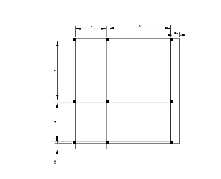
The alternate scheme of the layout after sorting out the irregularities pointed out in the given Moment resisting frame.
Question 3:
A multi-storey building with basement, with a quadrilateral (non symmetrical floor plan) plan as, has interior columns in an irregular (not in a grid) pattern in plan that serves architectural and functional considerations. Partition walls and interior beams supporting the slab have different layout in different stories. However, there is no constraint to the type, location and size of the lateral force resisting components and sub-systems on the perimeter. Proposals are to be made and justified for the choice of the lateral-load-resisting system and its foundation.
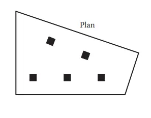
Observations:-
The observations from the architectural and structural perspective by just looking into the plan above.
- Floor plan- As can be observed by looking into the plan layout that the floor area is unevenly distributed,which is creating uneven distribution of gravity loads on either side of the floor level. If any inertial force induced at the floor level its effect should have equal influence on the other side of the same floor which is quite not possible in the given layout.
- Random internal columns- As we can see in the plan layout the columns are placed randomly which will cause the inefficient transference of lateral loads and unable to achieve desireable building response, columns are required to spread in the layout in such a symmmetrical way that the path for the load tranference becomes uniform and direct.
- Floor to floor variation in partition walls and beams- As mentioned above in the question statement that the height, cross sections of the beams and walls are changed on different floors of the structure which is causing the overall irregularity in the mass distribution of the building on the floor levels. This will lead to cause heavy distortion and distribution of lateral loads.
Measures adopted to stabilize the structure with the same architectural constraints-
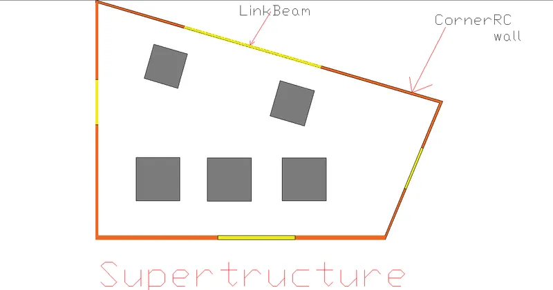
- As by looking into the plan we can see that the major proportion of the floor area is on the left side than the right side so,the heavy lateral loads are expected on the left side as well so,the corner shear walls are adviceable.
- Heavy torsional loads needs to be controlled by the lateral load systems, in that perspective also,the corner shear walls are suggested.
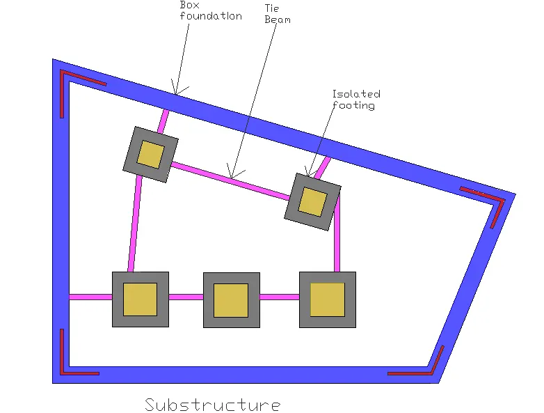
- Corner shear walls shall preferably be supported on the box foundation and the shear walls should be connected through link beams to transfer the shear from one to the other.
- The internal columns should be supported on the isolated footings and those isolated footings shall be connected through tie beams with the shear walls.
The schematic view of the suggession are as follows,