Creating a Residence Layout, Seating plan, Toilet and Utility room plan using AutoCad
1. Residence Plan.
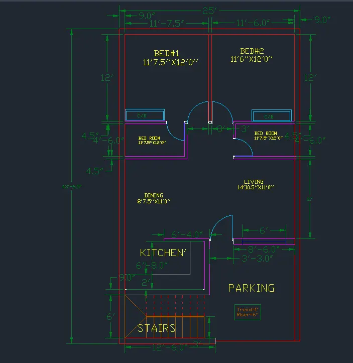
Aim:- To draft the layout of a given residence plan by considering the dimensions marked and assuimg the missing dimensions.
Introduction:- The layout of a residence plan is the planning of house in which different components of house is drawn as per the requirement and the feasibility of client.
Procedure:- To sketch of the residence layout the suitable tools are like xline(ver,hor),line,offset,extend,trim,fillet and many more.
The step by step procedure of the sketching is as follows:-
- Start with the autocad⮕set the units by typing ''UN''⮕change the length type from decimal to engineering and precision as 0'-0.0'' and select the insertion unit as inches.
- After setting up with the units ⮕set the limits of the screen⮕ type ''limmax'' and give the input coordinate as per the wide area required ⮕in the current project it seems 50'x50' is required so give coordinate as (50',50')
- press Z(zoom) then type a (all), now the screen is ready for drawing.
- give command as xline and draw a horizontal and vertical line, using that as a construction line
- start taking offsets from the construction line as per given dimensions⮕fillet the corners⮕trim off wherever required.
- using the same way create the bedrooms kitchen, toilet, parking area and all other components.
- After the completion of line drawing create different layers for giving different colours to different components in the layout.
- Now, mark the dimensions, and get matched with the given drawing, if it is not the same⮕ editing is always possible there.
- save the drawing and get screenshot using snipping tool.
Result:- The resultant sketch of the residence plan drawn is as follows,
2.Outdoor seating with canopy:-
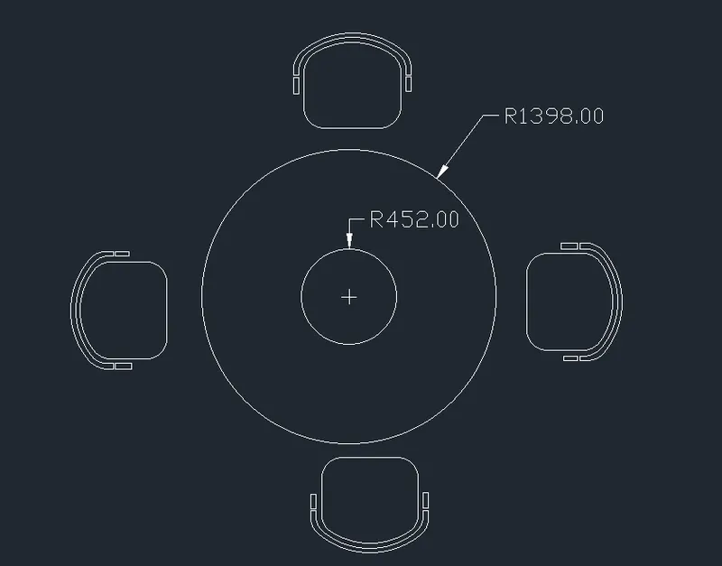
Aim:- To draw the given figure as seating with canopy.
Introduction:- Seating with canopy is something that is the arrangement of chairs with a table at the center made in or outside of the house and ca be used for different purposes such as to spend some quality time with the family, dining.
Procedure:- To draw the plan of seating with canopy the commands can be used are line, arc, circle,fillet etc. using the dimensions draw the given circles and assume the dimensions which are not given.
- Start with the autocad⮕set the units by typing ''UN''⮕change the length type from engineering to decimal and precision as 0.00 and select the insertion unit as milimeters.
- After setting up with the units ⮕set the limits of the screen⮕ type ''limmax'' and give the input coordinate as per the wide area required ⮕in the current project it seems 1500x1500 is required so give coordinate as (2500,2500)
- press Z(zoom) then type a (all), now the screen is ready for drawing.
- using circle(center,radius) draw a circle of radius 1398.00 and with the same centre draw one more circle of radius 452.00 ⮕from the arrangements shown in the given figure tablelike component is created.
- now, the creation of chair is required ,for the chair there are no specific dimensions are required.
- draw two lines at a gap of 900mm ,use draw arcs between two points and draw arc and create the seat of a chair as shown in the given figure⮕make it curvy at the corners using fillet tool(trim,radius).
- Dimensions are marked whereever it is required.
- After creation of the chair use copy selection and copy the same chair four times at their respective positions⮕Rotate the chair towards table at each location that is the seat of chair should face towards the table.
Result:- The resultant sketch of the given figure is as follows.
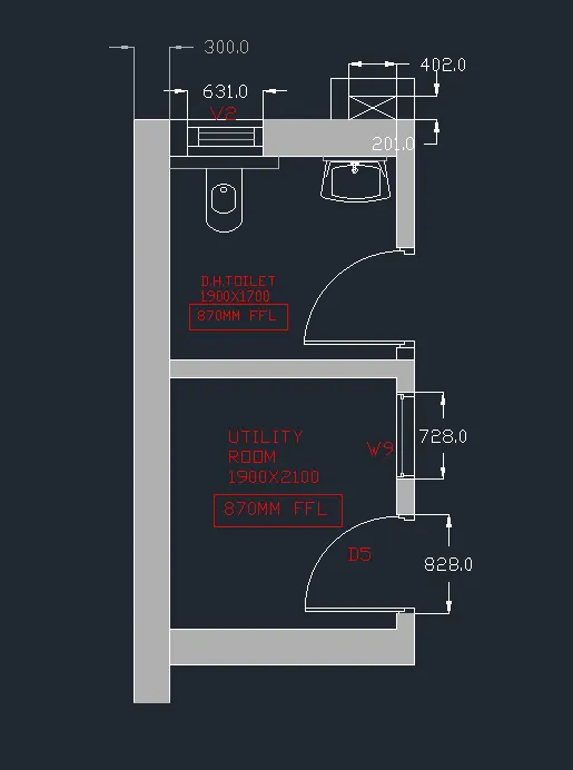
3.Part of toilers and utility room:-
Aim:- To draw a part of the plan showing part of toilers and utility room.
procedure:-To sketch of the given layout the suitable tools are like xline(ver,hor),line,offset,extend,trim,fillet and many more.
- Start with the autocad⮕set the units by typing ''UN''⮕change the length type from engineering to decimal and precision as 0.00 and select the insertion unit as milimeters.
- After setting up with the units ⮕set the limits of the screen⮕ type ''limmax'' and give the input coordinate as per the wide area required ⮕in the current project it seems 1500x1500 is required so give coordinate as (2500,2500)
- press Z(zoom) then type a (all), now the screen is ready for drawing.
- give command as xline and draw a horizontal and vertical line, using that as a construction line
- start taking offsets from the construction line as per given dimensions(outer wall as 300mm while inner wall is designated as 150mm)⮕fillet the corners⮕trim off wherever required.
- use hatching tool to hatch the walls using ''solid'' as shown in the given figure.
- After the creation of walls create windows, doors and ventilators whereever required.
- creation of sanitry components is also there in the given figure, use arc, line, fillet to create the washbasin and commode as in the given figure.
-
- Now, mark the dimensions, and get matched with the given drawing, if it is not the same⮕ editing is always possible there.
- save the drawing and get screenshot using snipping tool.
Result:- The resultant sketch of the residence plan drawn is as follows,