Creating Architectural and Structural model with 3D rendering using REVIT
1) Select the type of structure you want to build from one of the three below:
a. Multi-Unit Residential Apartment
b. Office Buildings
c. School
Here, In the above question we are Choosing to build a Multi-Unit Residential Apartment.
Aim:-To build a Rcc Structure of Multi-Unit Residential Apartment in our own location by following the guidelines from the Codal provisions of the National building code and the Gudelines from local authority as well.
2) Assume reasonable assumptions for geographic and location details for your project modeling. Based on assumptions and type of structure selected identify the modeling requirements from NBC.
As above we have selected to build a Rcc Structure of Multi-Unit Residential Apartment, The location here I want to select is my own city Patna,
The Geographical feautres of this location is such like Its a flat land area where usually pile foundation are prescribed by government for foundation. The building above 23 metres height is not allowed while upto 23 m one can construct on a 40 ft wide road.
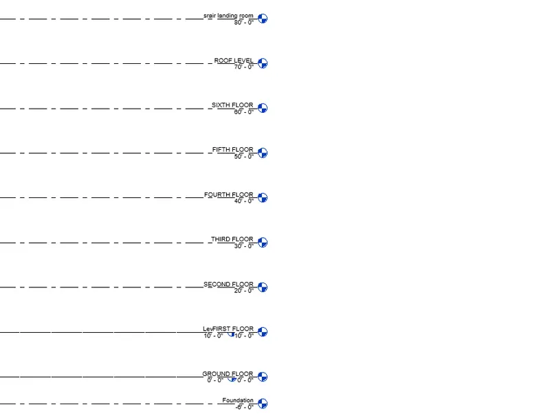
Let's agree upon to create a multi-storey Residential Apartment of G+5 floors of total height of 80 feet. The assumed plot size of 125'X120' on a 40feet wide road.
3) Using the structural model, include the following components based on the type of structure selected
a. Foundation – Isolated / Wall/Matt Foundation
b. Columns
c. Beams Connected to Columns
d. Roof Framing/ Truss
e. Floor / Decks
f. Floor Openings for Elevators and Stairs
Aim:- As we have decided abovethat we are going to create a multi-storey Residential Apartment of G+5 floors of total height upto 18metres. The assumed plot size of 120'X120' on a 40feet wide road.Here, in this question it is required to build the structural model of the structure like foundation,beam,column etc.
Procedure:-
- In our location it is mandatory for a high rise building to leave 20feet offset open space from the three sides while 30 feet open space from front side
- Open with the revit software,creating a file from the construction template.
- In the architecture tab first create the levels of floors and foundation level
- then,In the Structural tab mark out the Grids.
- Create all the elements required to be created in the Structural model like foundation footings,columns,beams.
- laying out of foundation at the desired grid intersections.
- In the structure tab Go to isolated in the foundation panel.
- select the size of the foundation required to be provided.
- then,select "at grids" and by selecting the grids mark the footings at all intersection points of the grid lines.
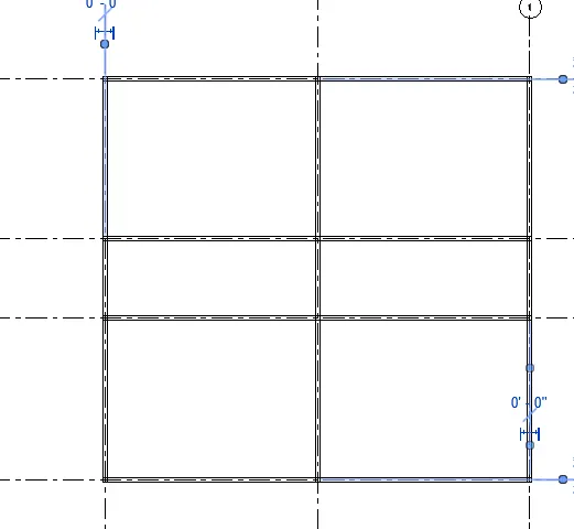
- Creation of Connecting beams along the grid lines.
- Go to column and select the shape and size of the column.
- Select to provide at the grids and the columns will be provides at the intersection locations.
- Similarly,Select the beam and choose to layout at the grids and provide along both the directions.
- Copy the beams from one level and copy them along all the required levels.
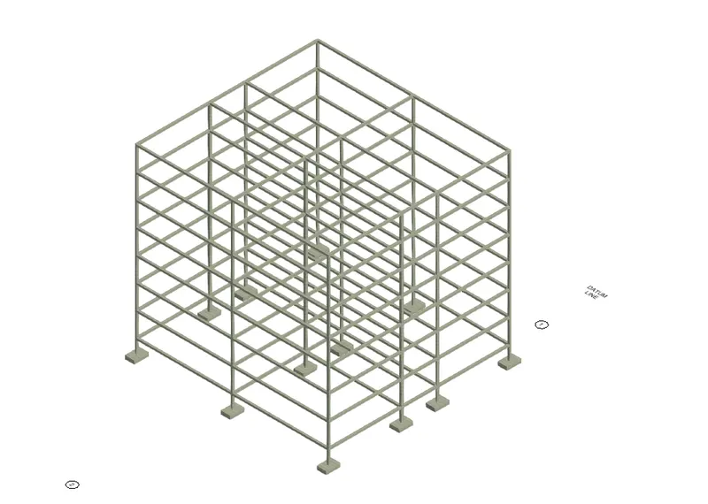
- 3D view of the structural model.
4) Using the architectural model, include the following components based on the type of structure selected
a. Wall Layout with appropriate material and finishing
b. Exterior façade with fancy finish
c. Interior partition walls to size rooms
d. Components to add details to a room ( Desk, Chair, Lighting, Plumbing fixtures)
e. Add components such as stairs Elevators
f. Have at-least one side of the building with curtain walls and glass panels
g. Include interior and exterior lighting fixtures
h. Place proper topographic components from outside ( Trees, Parking, Plants) to add details to the model
- Create an architectural template
- Create an architectural template to model the architectural elements like arrangement of spaces, placing components etc.
- Before Architectural modelling it is required to link the structural model into architectural model so that the coordination between the elements can be made.
- Linking of Structural model into Architectural model.
- Mark the grids one in transverse and one in longitudnal direction and locate the project base point at the intersection of both the grid lines.
- Go to insert tab choose link revit to link the structural model.
- Access the structural model file and select from the option to link from Auto-project base point to project base point.
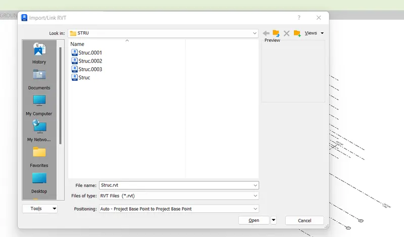
- Once the model is linked choose coordinate for both the files.
- Now,Go to Collaborate tab and choose copy/monitor, it will ask for selecting revit link select from ther model space and tjhen select for multiple.
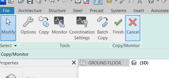
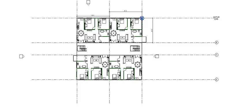
- then,selecting the grid lines from structural model link and then click finish, by doing so the grids are copied to our architectural model.
- Modelling of Architectural Elements.
- The copied grid lines will act as the reference for archtectural modelling.
- Create walls exterior and interior for the arrangement of the spaces.
- Then, place the components in the spaces.
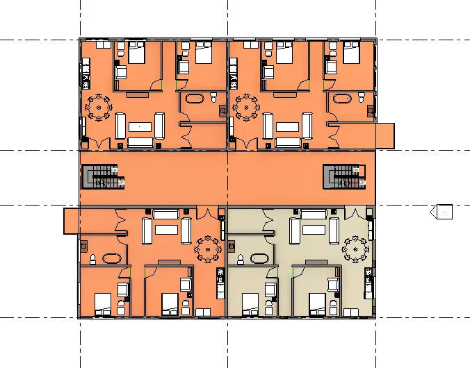
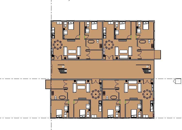
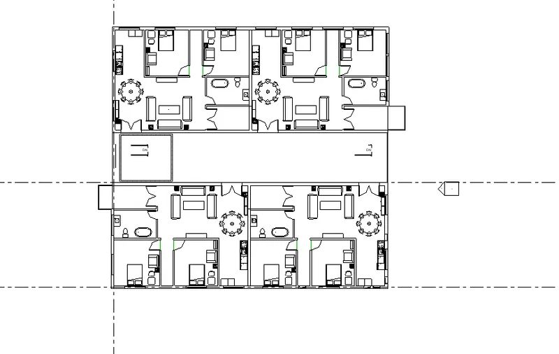
- Here, creating 4 flats at each floor.
- Copying the Architectural elements to other floors.
- select all the Architectural elements from the ground floor and copy into the clipboard then paste to assined levels.
- Thus, the Floor plans upto Six floors are created.
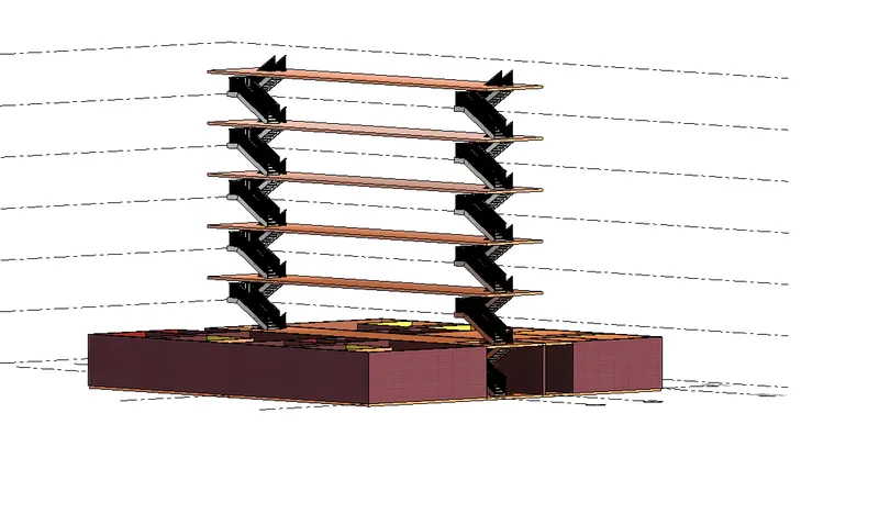
- Creation of stairs and Shaft for the same.
- Create the stair at one level and use the option to connect it for another levels.
- Go to architecture tab and select the shaft for shaft opening for circulation through stairs.
- Use pick lines option and pick the lines from stairs boundary and create the model for shaft opening and select the base point as ground floor and top constraint as Sixth floor.
- Floor Plans
- Ground floor plan.
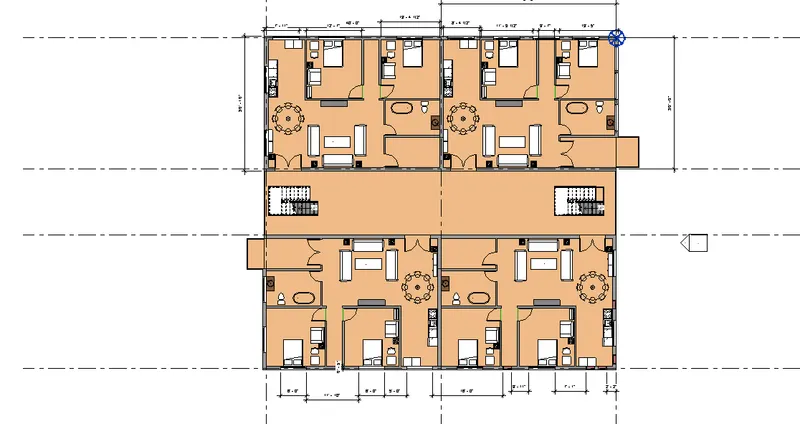
- First floor plan.
- Second floor plan.
- Third floor Plan.
- Fourth floor plan.
- Fifth Floor Plan.
- Sixth floor Plan.
- Elevations
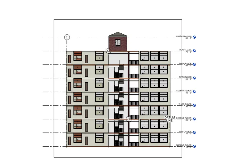
- Elevation from West side view.
- Elevation from East side view.
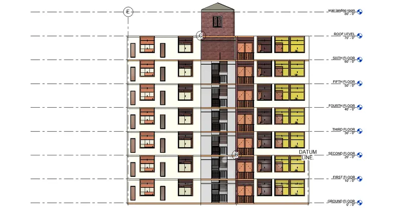
- Elevation from South side view.
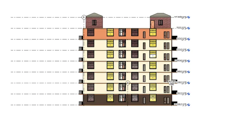
- Elevation from north side view.
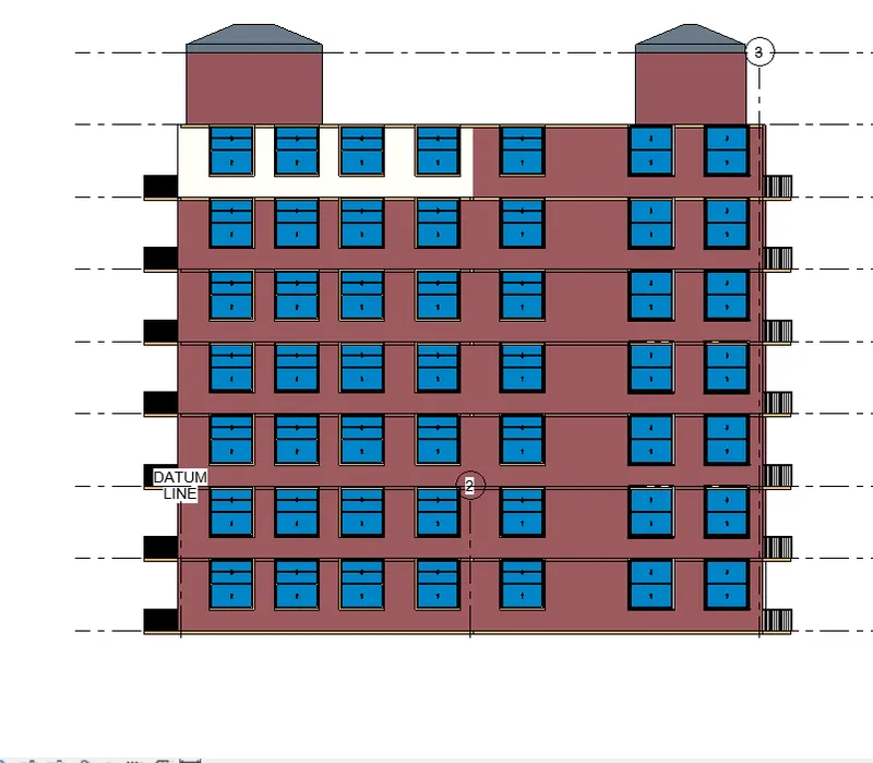
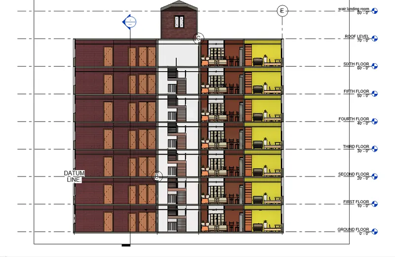
- Sections.
- Section along longitudnal direction.
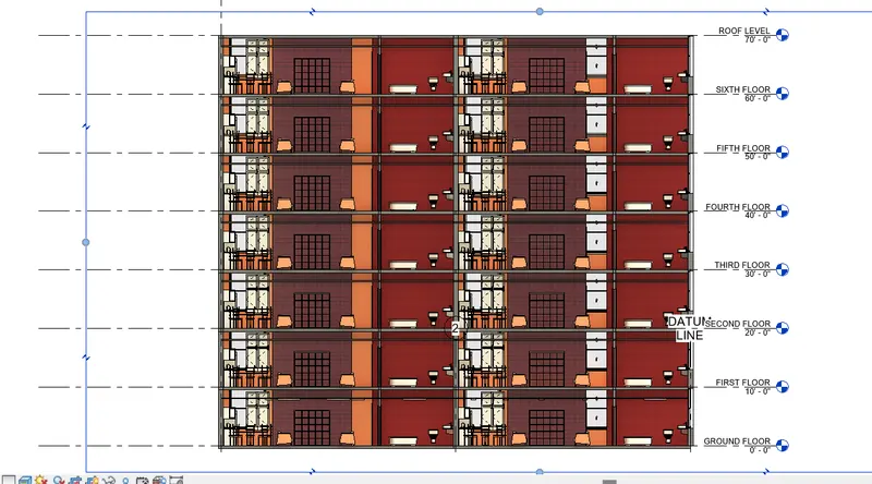
- Section along transverse direction.
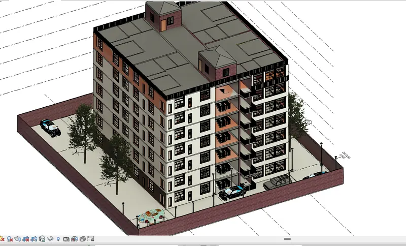
- 3D View
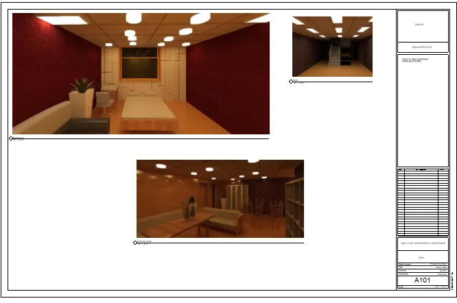
- RENDERED IMAGES.
- Bedroom view.
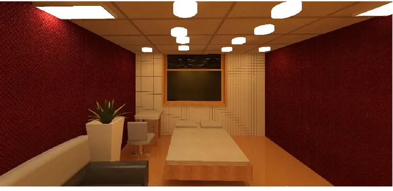
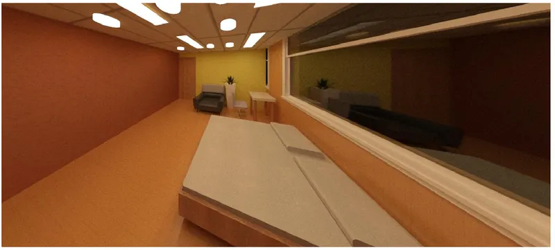
- Drawing hall View.
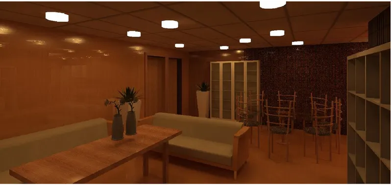
- Bathroom/Toilet view.
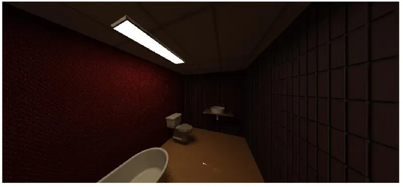
- Kitchen View.
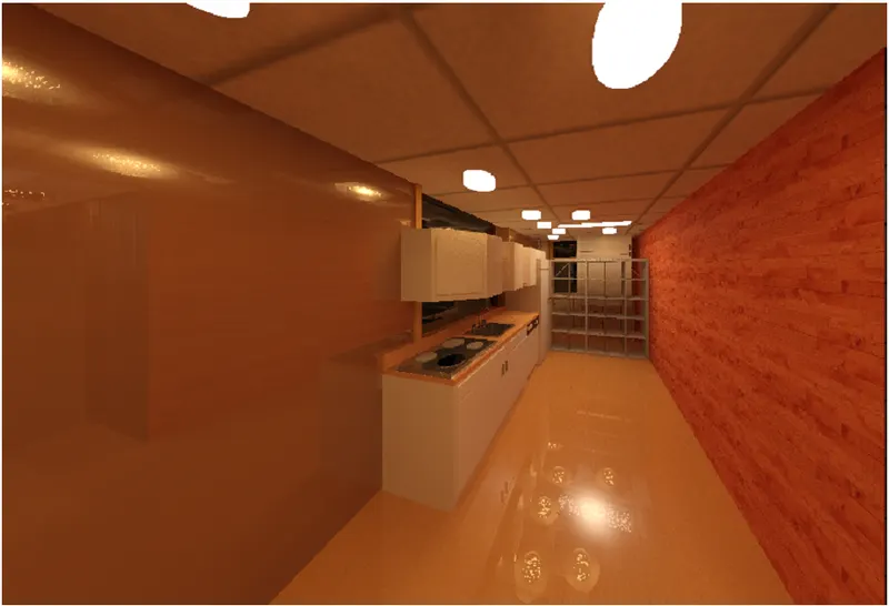
- Stair from coridoor view.
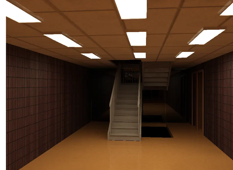
- Rendered image of the structural 3D model
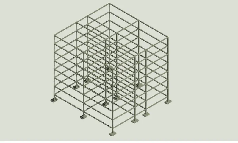
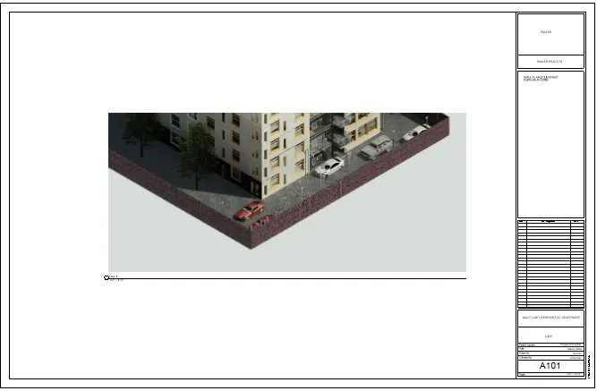
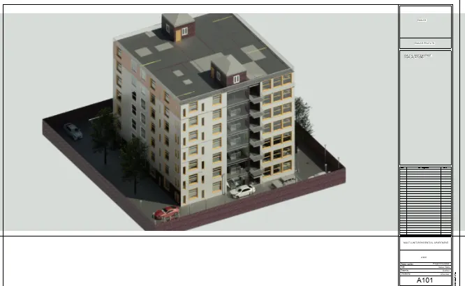
- 3D View 1
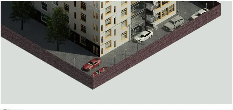
- 3D View 2
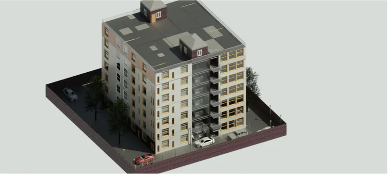
- Creating the Structural plans into Drawing Sheets.
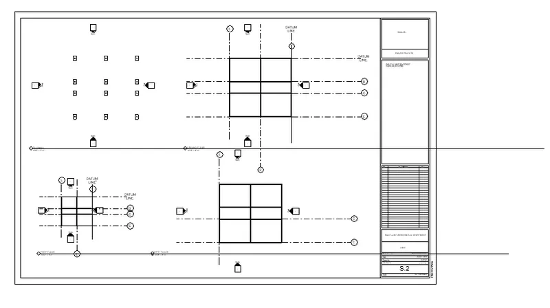
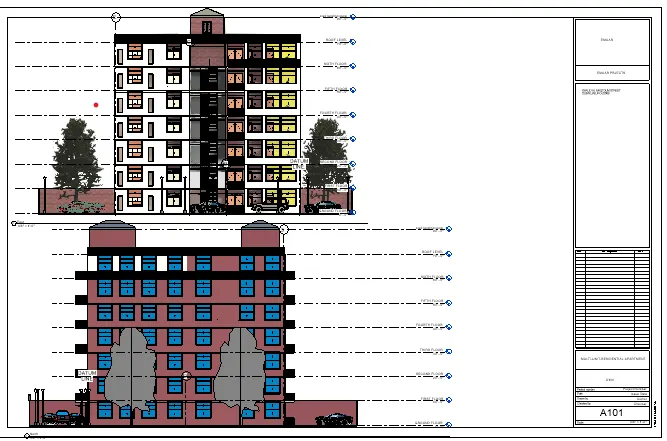
- Creating the ELEVATION VIEWS into Drawing Sheets.
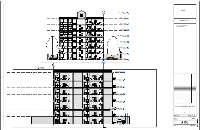
- Creating the SECTION VIEWS into Drawing Sheets.
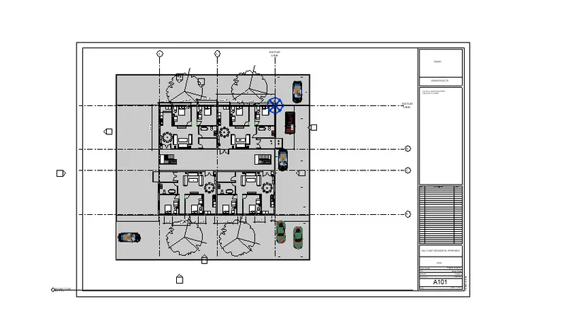
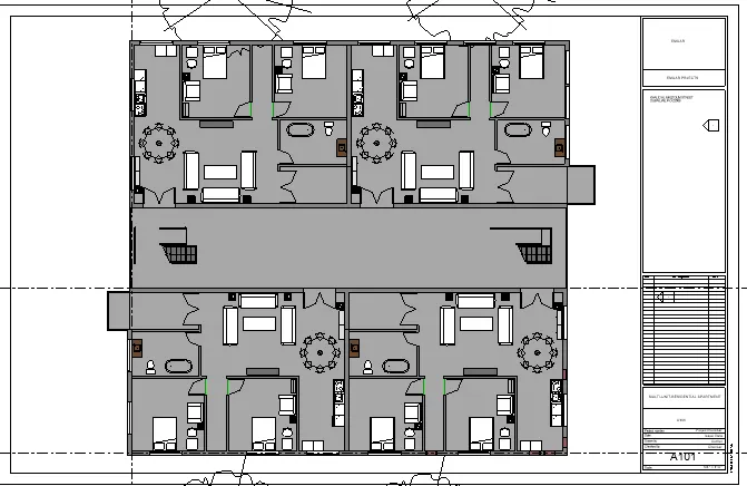
- Creating the FLOOR plans into Drawing Sheets.
- Creating the rENDERED IMAGES into Drawing Sheets.