Creating a Floor plan, Footing detail and Isometric view using AutoCad
- AIM:- To draw the given cross section C1 using Auto Cad.
- INTRODUCTION:-The given geometry and cross sections can be drawn using the various tools available in the auto cad and dimensions of the various components can also be shown as while creating such drawings like floor plan and footing detailing it requires to draw it in such a way that any other person can also read the drawings easily.In this section of drawings almost all major tools of the auto cad will be used.
- Load bearing wall-Load bearing walls are the walls other than the partition walls which are generally provided as the external walls and takes the load coming from the slab and other structural elements.
A load bearing wall is shown which rests on the stepped footing, the width of the wall is 0.3 and length is 1.0.
- PROCEDURE:-
for C1 drawing:- The given drawing is identified as cross section of load bearing wall over spread footing.Drawing the given using relative polar coordinate. The geometry can be easily created by using line command with different coordinate systems and the modification tools like offset.
- Result:-
The resultant drawing of C1 is as follows,all the dimensions of the geometry are also marked.
- AIM:- To draw the given cross section C2 using Auto Cad.
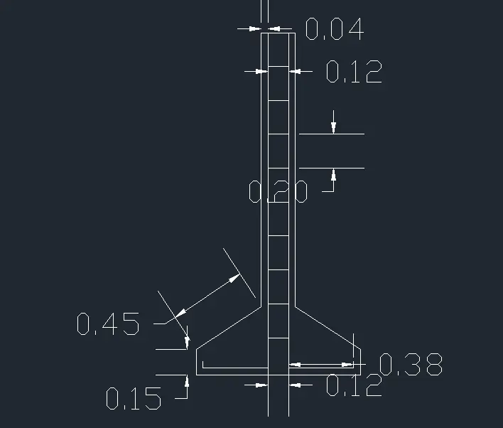
- INTRODUCTION:-The given geometry or cross section is identified as cross section of isolated footing.
Isolated footing:- It is a kind of shallow foundation which is designed in such a way that a single column weight rests on it. The reinforcement details are also shown like development length C/c distance of the stirrups etc.
PROCEDURE:- start with auto cad ⮕Advanced setup⮕set the units and precision of length and angles⮕use line tool⮕specify the first point anywhere in the drawing area⮕then use @(0.15<90)⮕@(0.38,0.25)⮕@(1.60<90), @(0.04<0) ,@(0.38<180), @(0.04<90), @(0.38,-0.25), @(0.15<270), @(0.38<0), @(0.04<90)⮕ also use offset (multiple)through a distance of 0.20 to draw c/c spacing of stirrups.
Result:-
The dimensions are also marked and the resultant image is as follows
- AIM:- To draw the given cross section C3 using Auto Cad.
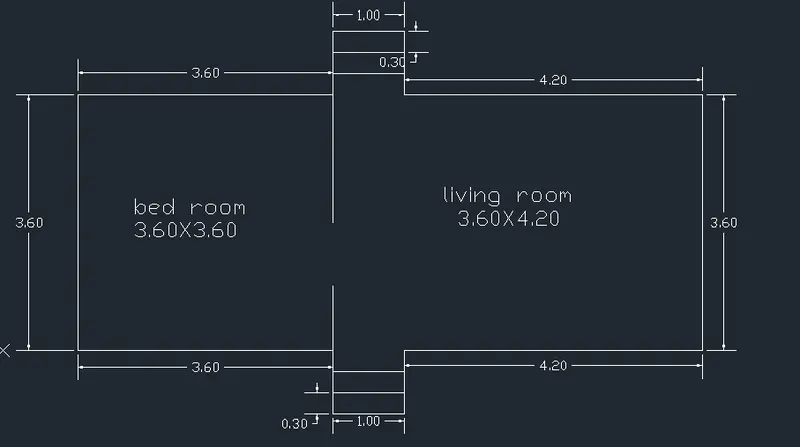
- INTRODUCTION:-The given geometry or cross section is identified as a line diagram of two bedroom with dimensions marked.The given plan can be easily sketched using line tool and the modifacation tools such as offset.
- PROCEDURE:- start with auto cad ⮕Advanced setup⮕set the units and precision of length and angles⮕use line tool⮕specify first point anywhere and start sketching with the lines using @(length<angle) and offset (multiple).
Result:-
The dimensions are marked and the resultant image of drawing is as follows
- AIM:- To draw the given cross section C4 using Auto Cad.
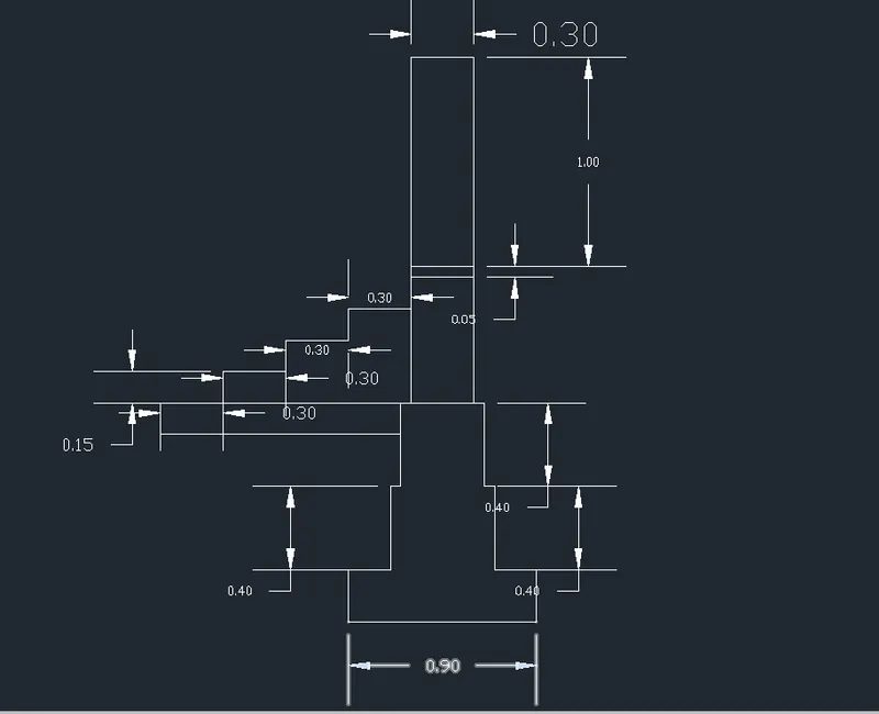
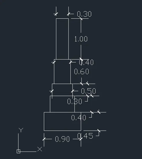
- INTRODUCTION:-The given geometry or cross section is identified as cross section of load bearing wall showing foundation details with dimensions marked.
load bearing wall-Load bearing walls are the walls other than the partition walls which are generally provided as the external walls and takes the load coming from the slab and other structural elements.
- PROCEDURE:- start with auto cad ⮕Advanced setup⮕set the units and precision of length and angles⮕use line tool⮕specify first point anywhere and use relative rectangular polar coordinate method to sketch the plan as it will be the most easy to draw using relative rectangular polar coordinate method .
- The coordinates identified from the drawing are @(0.90<0), @(0.45<90), @(0.15<180), @(0.40<90), @(0.05<180), @(0.30<90), @(0.05<180), @(0.60<90), @(0.05<180), @(0.60<90), @(1.0<90), @(0.30<180), @(1.0<270), @(0.05<180), @(0.30<270), @(0.05<180), @(0.40<270), @(0.05<180), @(0.45<270), @(0.15<180)⮕center⮕exit⮕dimensions are marked.
Result:-The resultant image of the drawing is as follows.
- AIM:- To draw the given Isometric view plan C5 using Auto Cad.
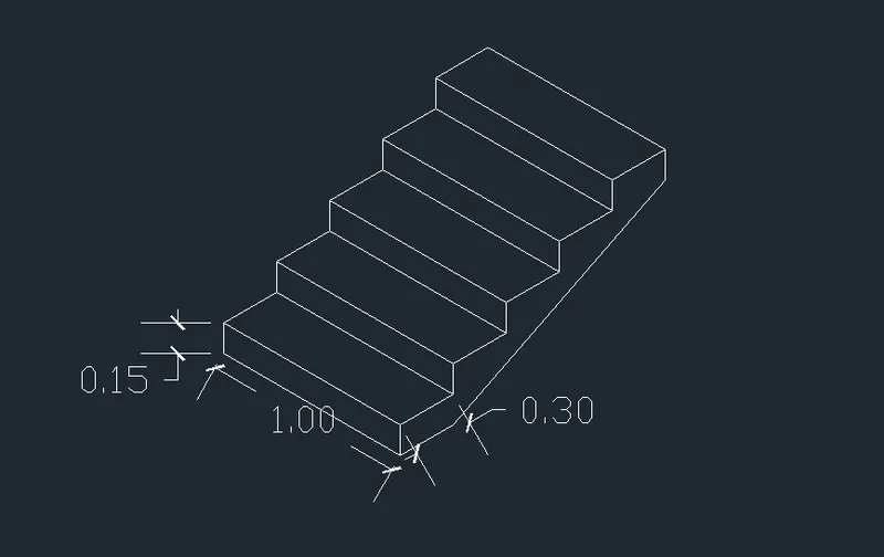
- INTRODUCTION:-The given geometry or cross section is identified as stairs which need to be drawn in isometric view with dimensions marked.
Stairs- Stair is a structural component of a building which is used for the vertical movement in the building.
- PROCEDURE:- start with auto cad ⮕Advanced setup⮕set the units and precision of length and angles⮕go to draft settings⮕uncheck the grid and snap radi button and the below isometric snap radiop button⮕then put ortho mode on⮕then use isometric tool to draft the given view.
- Result:- The resultant fig of the draft is shown below with the dimensions marked.
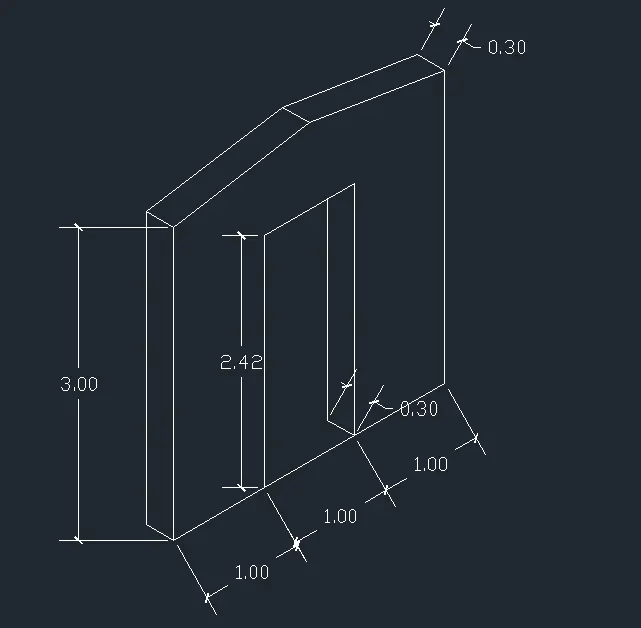
- AIM:- To draw the given Isometric view of gable wall/ drawing C6 using Auto Cad.
- INTRODUCTION:-The given geometry or cross section is identified as the gable wall with a door included which need to be drawn in isometric view with the dimensions marked.
Gable wall- Gable wall is a triangular portion of wall which are generally made under sloped roofs.
- PROCEDURE:- start with auto cad ⮕Advanced setup⮕set the units and precision of length and angles⮕go to draft settings⮕uncheck the grid and snap radio button and the below isometric snap radiop button⮕then put ortho mode on⮕then use isometric tool to draft the given view.
Result:-The resultant view of the drafted image is shown below,