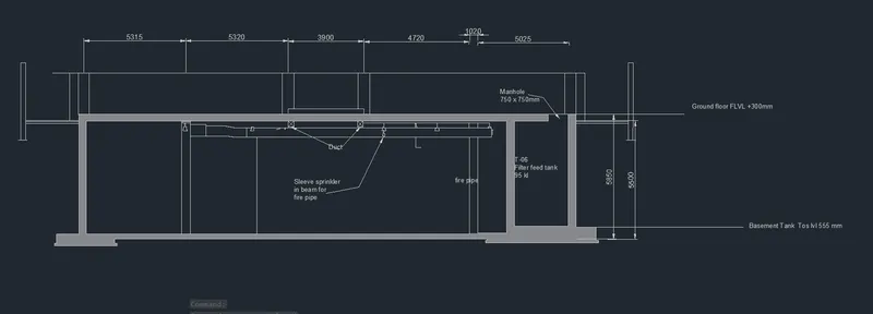
Creating Kitchen layout, Hatching of Architectural elements and sectional view of an Industrial Building in AutoCad
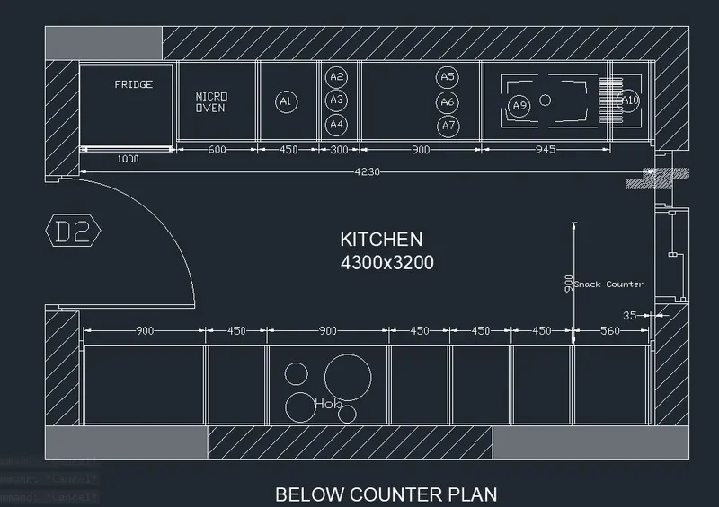
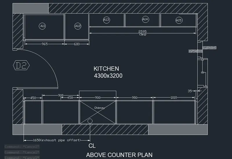
1.Create the layouts of the Kitchen and provide hatches pattern as shown. Also, use blocks wherever required. Provide appropriate dimensions in the plan. Assume the size of doors, appliances and others as per the standards.
Aim:-To create the given kitchen plan layout and providing hatch patterns as shown in the figure.
Introduction:-
Hatching- Hatching is nothing but just filling an enclosed area with a particular pattern and it is used in autocad to show the realistic view of the objects,that is why for different components in the drawing different hatch patterns are available or it can be customised as well.
Procedure:-
- Start with the autocad⮕ set the unit type as decimal with the precision 0 and the insertion unit as milimeters⮕analyse the screen required for the drawing and set the screen size using limmax⮕Zoom⮕ all⮕ now the screen is ready for the drawing.
- creating the given plan layout using the draw commands like line,rectangle, circle and the modify commands such as offset,trim ,extend,fillet etc.
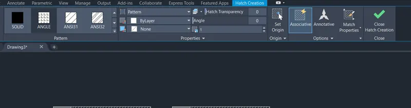
- Mark the dimensions and place the texts wherever required⮕Now to provide the hatch patterns type HA for the command "hatch" ⮕choose the hatch pattern⮕change the scale,angle,transparency if required so that the pattern looks good in the site provided⮕close hatch creation⮕match with the given figure ⮕if it is look alike then take the snap using snipping tool.
Result:- The resultant snap of the autocad drawing is as follows,
Final complete drawing
2. Create the elevation of the plan created in the Challenges 7 and apply proper hatch in the walls, doors, windows, and other architectural elements. Refer to the dimensions in Plans and sections in Challenges 7.
Aim:-To create the given kitchen plan layout and providing hatch patterns as shown in the figure.
Introduction:-
Hatching- Hatching is nothing but just filling an enclosed area with a particular pattern and it is used in autocad to show the realistic view of the objects,that is why for different components in the drawing different hatch patterns are available or it can be customised as well.
Procedure:-
- Start with the autocad⮕ set the unit type as decimal with the precision 0 and the insertion unit as milimeters⮕analyse the screen required for the drawing and set the screen size using limmax⮕Zoom⮕ all⮕ now the screen is ready for the drawing.
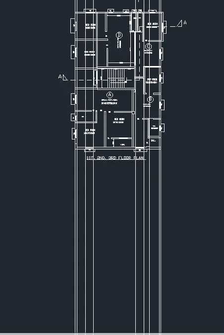
- For creating the elevation drawing of a plan the procedure is to draw vertical lines below the plan using xline(ver)⮕drawing horizontal lines with the refrence of vertical lines and by considering the height such as plinth height,sill level, lintel level,door and windows level create the sections and remove/trim the undesireable line
- Different components in the elevation or section can be shown in different way like windows and doors can be shown in rectangular section while for sunshade using sloped pattern.
- mark the required texts in the drawing as directed in the given figure.
Result:-
The resultant snaps of the drawings are as follows,
Drawing of vertical lines to create elevation from the plan
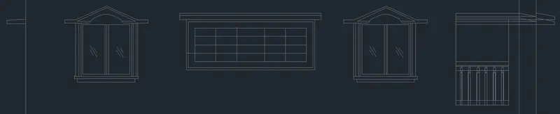
creation of windows and other components
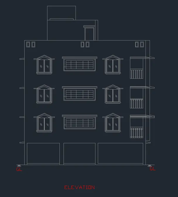
copying the same for above floors
Final elevation output
3. Create the section view of an industrial building as shown in Figure. Provide appropriate hatches and dimensions wherever required. Also, provide annotations to the drawing.
Aim:-To create the section view of an industrial building as shown in Figure
Introduction:-
Hatching- Hatching is nothing but just filling an enclosed area with a particular pattern and it is used in autocad to show the realistic view of the objects,that is why for different components in the drawing different hatch patterns are available or it can be customised as well.
Procedure:-
- Start with the autocad⮕ set the unit type as decimal with the precision 0 and the insertion unit as milimeters⮕analyse the screen required for the drawing and set the screen size using limmax⮕Zoom⮕ all⮕ now the screen is ready for the drawing.
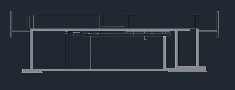
- using the line tool create the section given as in the figure.
- after creation of the section plan mark the dimensions and provide the necessary texts. Now to provide the hatch patterns type HA for the command "hatch" ⮕choose the hatch pattern⮕change the scale,angle,transparency if required so that the pattern looks good in the site provided⮕close hatch creation⮕match with the given figure ⮕if it is look alike then take the snap using snipping tool.
Results:-
creation of the section using draw tools such as line,polyline.
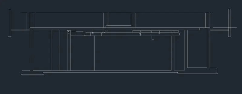
providing hatching for the required components.
final output with texts and dimensions