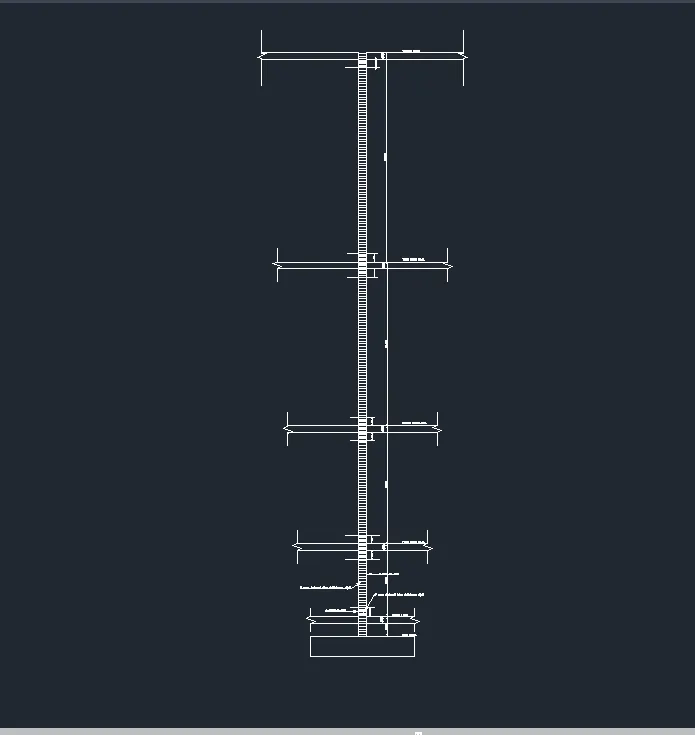
Reinforcement detailing of Columns from ETABS output
Reinforcement detailing of columns in Etabs 2018.
The ETABS file for a G+4 building is provided. Run the analysis and design the RCC Moment Resisting Frame. The following challenge deals specifically with two columns at the following grid intersections.
- 3A
- 3B
- Provide details of longitudinal reinforcement for the two columns, from foundation to terrace level. Sketch the column cross sectional & elevation details or draft it using autocad software.
- Show shear reinforcement & lapping details as per special confining reinforcement provision of clause 8.1 of IS 13920 - 2016.
Aim:- To analyze and extract the area of reinforcement value for column to draw the reinforcement detailings in the auto Cad software for the column.
Introduction:-
Column- A column can be defined as a vertical member which transfers the loads from slab and beams to the foundation,a column can also be defined as a compression member which acts to transfer the axial loads.
Column Reinforcement:- Two kinds of reinforcements are provided in the column one is longitudnal reinforcement while the other is Shear reinforcements.
Procedure:-
- Download the attached Etabs model file and open it up using the sotware.
- Perform Analysis of the model.
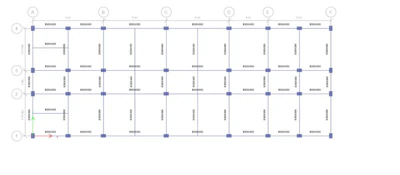
- Perform the analysis of the model by pressing the F5 key or by pressing the play button available in the tool palletes,wait for the analysis to get completed till the deflected shpe of the model appears.
- View the deflected model in 3D.
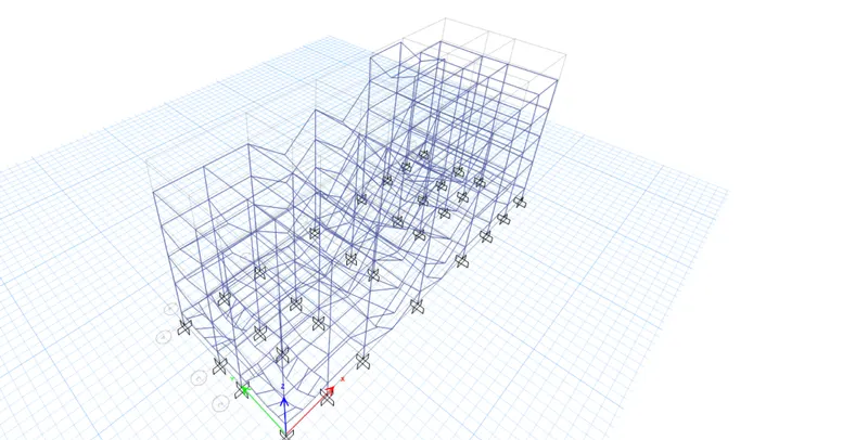
- After the completion of the analysis of the model, Select the independent view of the column whose design is required.
- Select the columns at Grid 3A and 3B, and set to view the selected objects only.
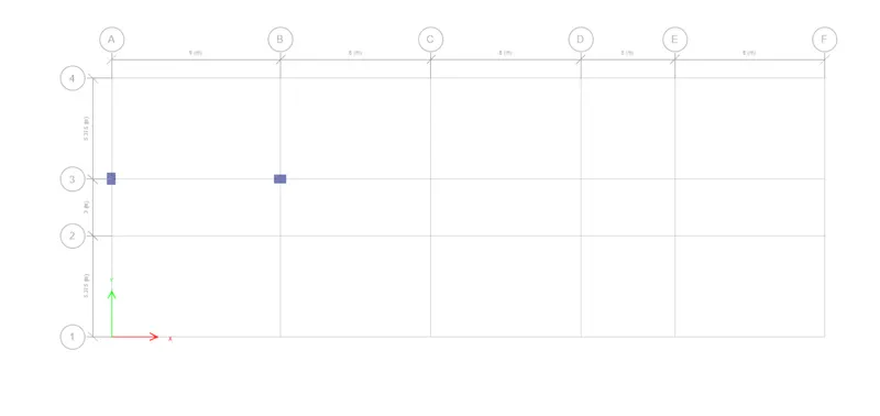
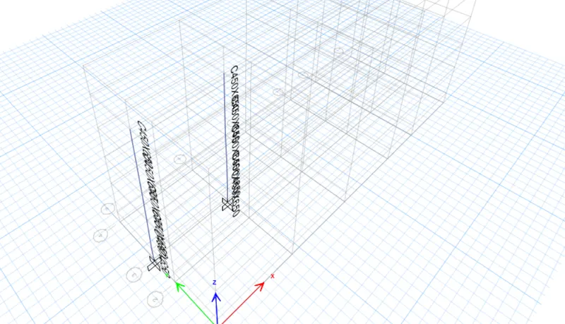
- Now, we can run the frame design,click over the icon of the run the concrete frame design.
- It will automatically starts the designing process.
- Once the designing process is completed set the view in elevation view for the clear view of area of reinforcements along the column height.
- Go to elevation option tab⮕Select A and ⮕apply ⮕select 3⮕apply.
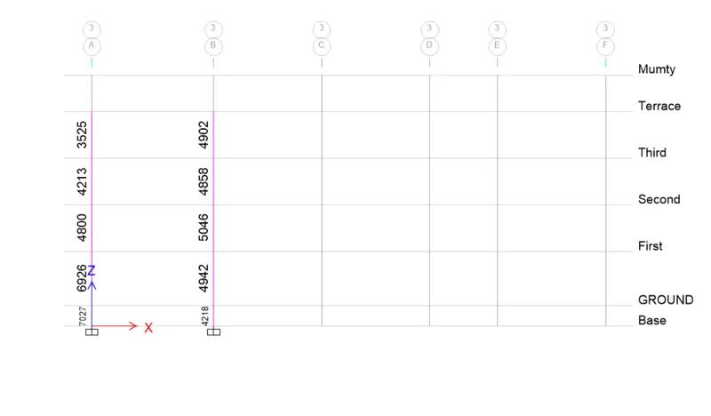
- The following view can be arrived with.
- The longitudnal area of required reinforcement in mm2 for 3A and 3B columns are as follows.
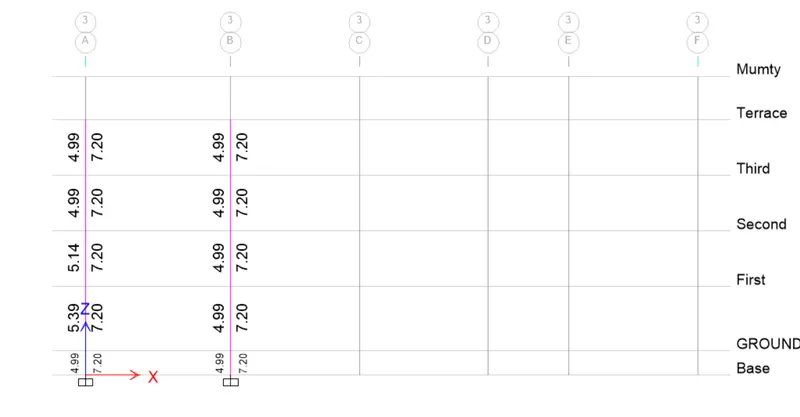
- The area of required shear reinforcement in cm2 for 3A and 3B columns are as follows.
- Calculation of the reinforcement details for grid 3A column.
As we can see from the etabs result for the area of longitudnal reinforcement the,
Ast max= 7027 mm2,we know that as per the codal provisions the longitunal reinforcement designed for columns has to be designed for the maximum area of renforcement.
So, for Ast=7027,we have to adjust the Ast with the available rebars in the market.
let's provide 10-32T for the longitudnal reinforcement, 10-32T counts for 8038mm2 which is greater than our required Ast ,hence ok.
- calculation of the anchorage length.
- For 32 mm dia bars,
Formulae for the anchorage length as per IS 13920
Anchorage length=Ld+10db, Where Ld is development length and db is nothing but the diameter of the bar for which we are calculating the anchorage length.
Ld can be calculated as, Ld = φ σst/4τ bd
In the model,section properties arte provided are concrete of M30 grade while steel rebar for longitudnal reinforcement of HYSD415 are provided.
τ bd value from the IS 456:2000 ,we know=1.875 (for the deformed bars in compression)
so,Ld for T-32 rebar,
Ld=((32x415)/(4x1.875))
Ld=1770 mm.
Anchorage length=Ld+10db=1770+32*10=2090mm
- Special confining reinforcement from IS 13290-2016, clause 8.1
From there suggessions we have,
- L0 should be not less than,
L0 is nothing but a particular distance from the top of the beam or bottom of the beam into the column upto which confined reinforcing is suggested by the codal provisions.
- larger column dimension which is 650 mm
- 1/6 of the clear span of the column. (whichever is greater)
- Shorter column dimension which is 450 mm.
So, L0 is considered to be 650mm
2.Confinement spacing nbot more than,
- 1/4 of smaller column dimension.=(1/4)x450=112.5mm
- 6 times dia of column of main bar=6x32=192 mm (whichever is lesser)
- 100mm
So, 100 mm is considered.
Note:-As we are getting the same area of shear reinforcement requirement all along the height of the building. It suggests that the shear reinforcement is not required but, IS code has suggested to provide the minimal shear reinfocements in that perspective so,
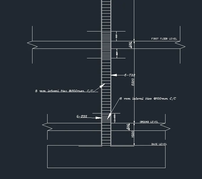
- Provide 8 mm lateral ties @200 mm C/C
- In the confined zone Provide 8 mm lateral ties @100mm C/C
Cover in the column is considered to be =40mm
and for the anchorage length in the foundation cover considered is=50 mm
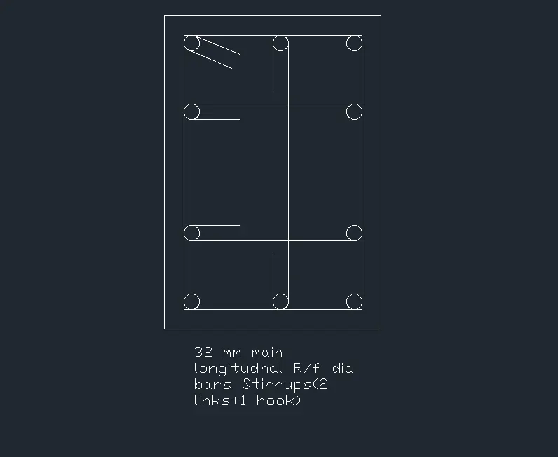
- The Plan view of the Column Reinforcement Detailing are as follows,
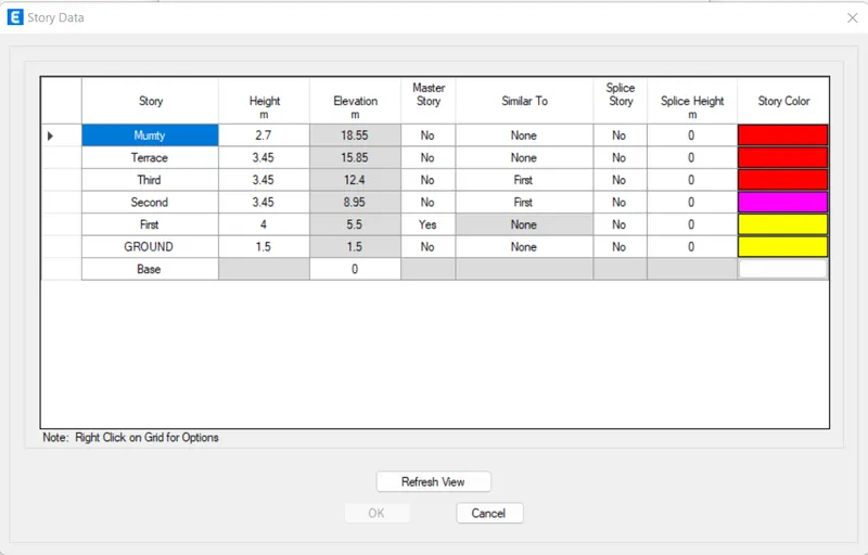
- Story assignment data used for drawing the elevation of the column
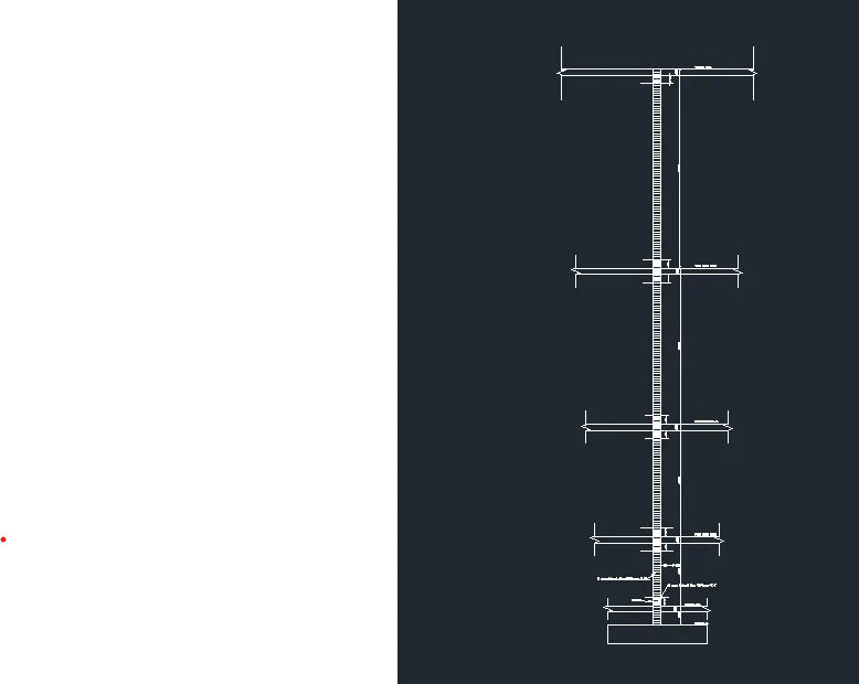
- The detailing of the reinforcement in the auto Cad software are as follows,
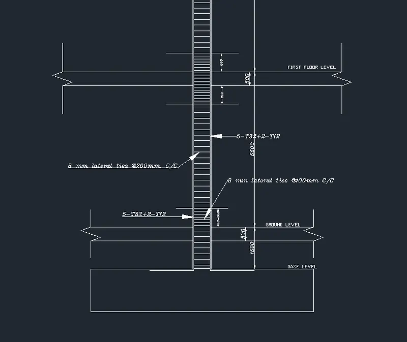
- From Base to Ground level and upto first floor level,
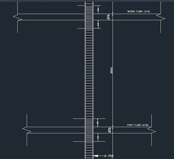
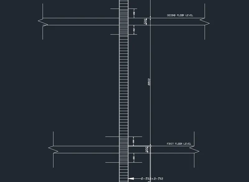
- From first floor level to second floor level,
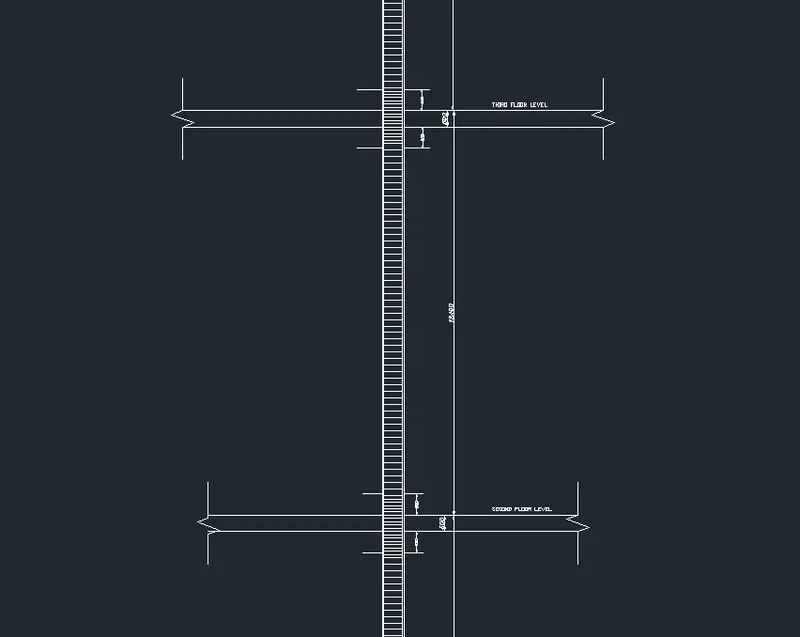
- From second floor level to third floor level,
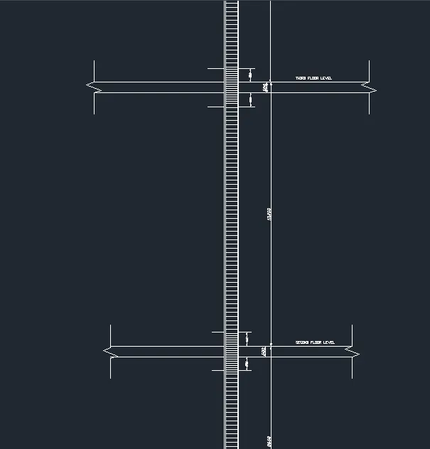
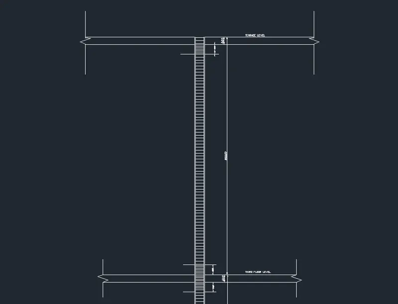
- From third floor level to terrace level
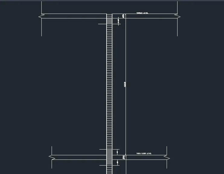
- From base level to terrace level,
- Calculation of the reinforcement details for grid 3B column.
As we can see from the etabs result for the area of longitudnal reinforcement the,
Ast max= 5046 mm^2,we know that as per the codal provisions the longitunal reinforcement designed for columns has to be designed for the maximum area of renforcement.
So, for Ast=5046 mm^2,we have to adjust the Ast with the available rebars in the market.
let's provide 8-25T for the longitudnal reinforcement, 2-12T counts for 5132 mm^2 which is greater than our required Ast ,hence ok.
- calculation of the anchorage length.
- For 32 mm dia bars,
Formulae for the anchorage length as per IS 13920
Anchorage length=Ld+10db, Where Ld is development length and db is nothing but the diameter of the bar for which we are calculating the anchorage length.
Ld can be calculated as, Ld = φ σst/4τ bd
In the model,section properties arte provided are concrete of M30 grade while steel rebar for longitudnal reinforcement of HYSD415 are provided.
τ bd value from the IS 456:2000 ,we know=1.875 (for the deformed bars in compression)
so,Ld for T-32 rebar,
Ld=((32x415)/(4x1.875))
Ld=1770 mm.
Anchorage length=Ld+10db=1770+32*10=2090mm
Similarly, anchorage length of 12 mm rebar=664+10*12=784mm
- Special confining reinforcement from IS 13290-2016, clause 8.1
From there suggessions we have,
- L0 should be not less than,
L0 is nothing but a particular distance from the top of the beam or bottom of the beam into the column upto which confined reinforcing is suggested by the codal provisions.
- larger column dimension which is 650 mm
- 1/6 of the clear span of the column. (whichever is greater)
- Shorter column dimension which is 450 mm.
So, L0 is considered to be 650mm
2.Confinement spacing nbot more than,
- 1/4 of smaller column dimension.=(1/4)x450=112.5mm
- 6 times dia of column of main bar=6x32=192 mm (whichever is lesser)
- 100mm
So, 100 mm is considered.
Note:-As we are getting the same area of shear reinforcement requirement all along the height of the building. It suggests that the shear reinforcement is not required but, IS code has suggested to provide the minimal shear reinfocements in that perspective so,
- Provide 8 mm lateral ties @200 mm C/C
- In the confined zone Provide 8 mm lateral ties @100mm C/C
Cover in the column is considered to be =40mm
and for the anchorage length in the foundation cover considered is=50 mm
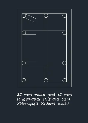
- The plan view of the longitudnal reinforcement are as follows,
- Story assignment data used for drawing the elevation of the column
- The detailing of the reinforcement in the auto Cad software are as follows,
- From Base to Ground level and upto first floor level,
- From first floor level to second floor level,
- From second floor level to third floor level,
- From third floor level to terrace level
- From base level to terrace level,