Drafting of various geometries using Chamfer, Fillet tool in AutoCad
1.for fig1.
Aim:- To draw the given geometry using Auto Cad.
Introduction:- Auto Cad is a computre aided drawing softaware which comes with a lot no of drawing tools and modification tools, and Auto Cad can be used to draft in 2D and in 3D as well.Auto Cad is developed by the company named as Autodesk,each year the company launches its upgraded version in the open market.As this software is very costly our project here is produced by the autodesk student version.
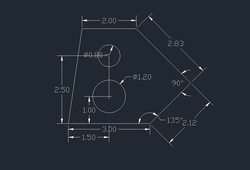
Procedure:- The fig. 1 is identified as the polygon geometry under which two circles are embedded of different diameter,
Get started with the autocad⮕go to utilities to setup the units ⮕enter
units⮕select decimal⮕with precision as 0.00⮕select angle in decimal degrees⮕with precision as 0⮕finish up with the units setting
use the line command⮕the coordinates used to draw the line geometry here is @(3<0)⮕ @(2.1288<45)⮕@(2.8300<135)⮕@(2.000<180)⮕close.
use circle command to draw the given circle⮕bottom circle is identified as the centre at 1 unit from the y axis and 1.5 units from the x asis ⮕using circle(center, diameter)circle drawn with a diameter of 1.2 units.the second circle centre is in the vertical line of the bottom circle at a distance of 1.5 units from the bottom circle,using⮕(center, diameter)circle drawn with a diameter of 0.8 units.
Now, the sketch of the model is ready⮕go to annotation for dimensioning⮕select linear dimension to mark the dimensions line segments⮕select angular dimensions to mark the angles between two lines⮕use diameter to mark the diameters of the respective circles.
Result:- The resultant image of the fig is shown below
2.for fig2.
Aim:- To draw the given geometry using Auto Cad.
Introduction:- Auto Cad is a computre aided drawing softaware which comes with a lot no of drawing tools and modification tools, and Auto Cad can be used to draft in 2D and in 3D as well.Auto Cad is developed by the company named as Autodesk,each year the company launches its upgraded version in the open market.As this software is very costly our project here is produced by the autodesk student version.
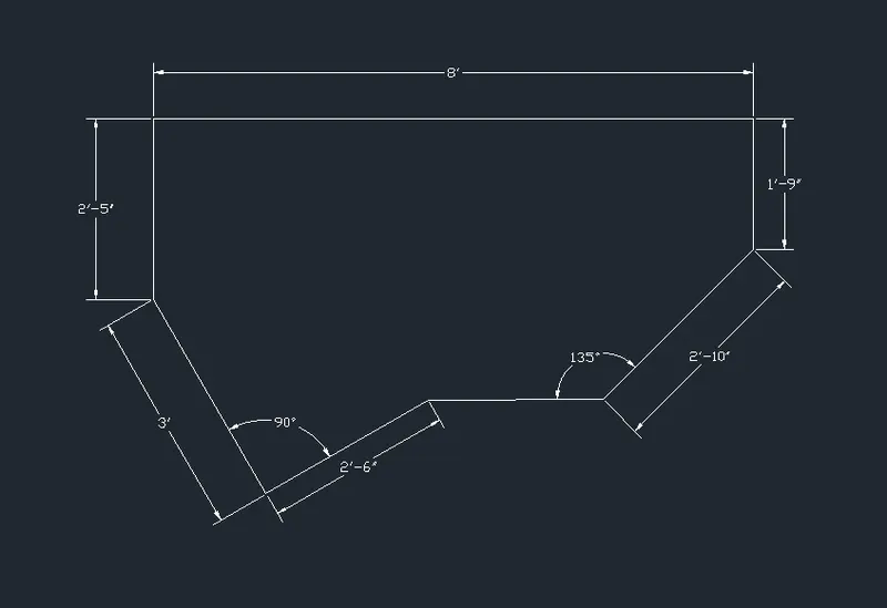
Procedure:- The fig. 2 is identified as the simple line geometry which can efficiently created by line command or polygon command in architectural units.
Get started with the autocad⮕go to utilities to setup the units ⮕enter
units⮕select architectural⮕with precision as 0'-00''⮕select angle in decimal degrees⮕with precision as 0⮕finish up with the units setting
use the line command⮕the coordinates used to draw the line geometry here is @(2'10<45)⮕ @(1'9<90)⮕@(8'0<180)⮕@(2'5<270)⮕@(3<135) ⮕@(2'6<45)⮕ Join the left portion free hand with end snap object on.
select the annotation tool from the menu bar⮕modify it for change in scale factor so that dimensions on paper can be clearly visible⮕set the primary units and precision as set as per the unit settings oin utilities⮕choose dimlinear for marking the linear dimensions⮕choose dimangular to mark the angular dimensions.
Result:- The resultant image of the procedure followed is shown below
3.for fig3.
Aim:- To draw the given geometry using Auto Cad.
Introduction:- Auto Cad is a computre aided drawing softaware which comes with a lot no of drawing tools and modification tools, and Auto Cad can be used to draft in 2D and in 3D as well.Auto Cad is developed by the company named as Autodesk,each year the company launches its upgraded version in the open market.As this software is very costly our project here is produced by the autodesk student version.
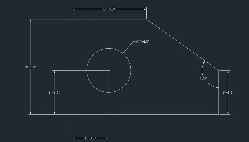
Procedure:- The fig. 3 is identified as the simple enclosed line geometry with a circle drawn inside which can efficiently created by line command or polygon command in architectural units.
Get started with the autocad⮕go to utilities to setup the units ⮕enter
units⮕select architectural⮕with precision as 0'-00''⮕select angle in decimal degrees⮕with precision as 0⮕finish up with the units setting
use the line command⮕the coordinates used to draw the line geometry here is @(5'0.1<0)⮕ @(1'6<90)⮕escape nd again go to the starting point⮕@(3'3<90)⮕@(2'6.5<0)⮕Join the left portion free hand with end snap object on.
select the annotation tool from the menu bar⮕modify it for change in scale factor so that dimensions on paper can be clearly visible⮕set the primary units and precision as set as per the unit settings oin utilities⮕choose dimlinear for marking the linear dimensions⮕choose dimangular to mark the angular dimensions.
Result:- The resultant image of the procedure followed is shown below
4.for fig4.
Aim:- To draw the given geometry using Auto Cad.
Introduction:- Auto Cad is a computer aided drawing softaware which comes with a lot no of drawing tools and modification tools, and Auto Cad can be used to draft in 2D and in 3D as well.Auto Cad is developed by the company named as Autodesk,each year the company launches its upgraded version in the open market.As this software is very costly our project here is produced by the autodesk student version.
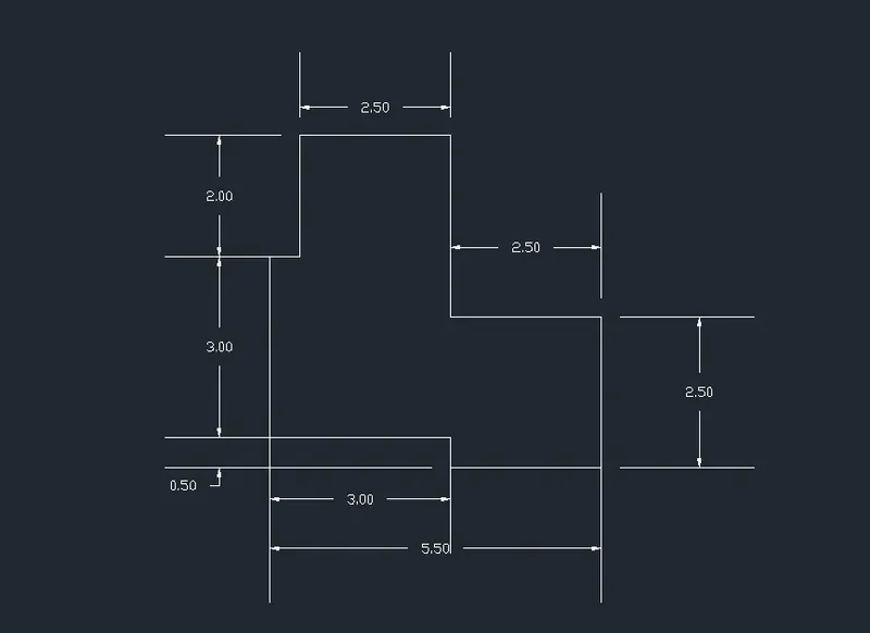
Procedure:- The fig. 4 is identified as the simple line geometry with which can efficiently created by line command or polygon command in architectural units and using the rectanular polar coordinate method.
Get started with the autocad⮕go to utilities to setup the units ⮕enter
units⮕select decimal⮕with precision as 0.00⮕select angle in decimal degrees⮕with precision as 0⮕finish up with the units setting
use the line command⮕the coordinates used to draw the line geometry here is @(5.50<0)⮕
@(2.50<90)⮕@(2.50<180)⮕@(2.50<90)⮕@(2.50<90)escape nd again go to the starting point⮕@(3<90)⮕@(0.5<0)⮕@(2<90)⮕@(2.50<0)Join the left portion free hand with end snap object on.⮕
select the annotation tool from the menu bar⮕modify it for change in scale factor so that dimensions on paper can be clearly visible⮕set the primary units and precision as set as per the unit settings oin utilities⮕choose dimlinear for marking the linear dimensions⮕choose dimangular to mark the angular dimensions.
Result:- The resultant image of the procedure followed is shown below,
5.for fig5.
Aim:- To draw the given geometry using Auto Cad.
Introduction:- Auto Cad is a computer aided drawing softaware which comes with a lot no of drawing tools and modification tools, and Auto Cad can be used to draft in 2D and in 3D as well.Auto Cad is developed by the company named as Autodesk,each year the company launches its upgraded version in the open market.As this software is very costly our project here is produced by the autodesk student version.
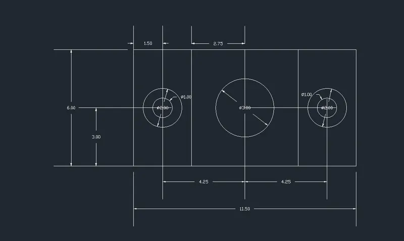
Procedure:- The fig. 5 can be drawn using line command and circle command with the help of coordinatew system as rectangular polar coordinate method which can efficiently create the desired geometry.
Get started with the autocad⮕go to utilities to setup the units ⮕enter
units⮕select decimal⮕with precision as 0.00⮕select angle in decimal degrees⮕with precision as 0⮕finish up with the units setting
use the line command⮕the coordinates used to draw the line geometry here is @(11.50<0)⮕
@(6<90)⮕@(11.50<180)⮕close ⮕locate the center of the central circle whose diameter is 3 units⮕center is located as the center of the rectangular geometry⮕draw circle using circle(center,diameter) ⮕locate the center of left side and right side circle whgich is at a distance of 4.25 units from the center of central circle⮕mark the centre points and using circle(center,diameter) draw circle of respective diameters at the both sides.
now, the sketch is completed ⮕
select the annotation tool from the menu bar⮕modify it for change in scale factor so that dimensions on paper can be clearly visible⮕set the primary units and precision as set as per the unit settings oin utilities⮕choose dimlinear for marking the linear dimensions⮕choose dimangular to mark the angular dimensions.
Result:- The resultant image of the procedure followed is shown below,
6.for fig6.
Aim:- To draw the given geometry using Auto Cad.
Introduction:- Auto Cad is a computer aided drawing softaware which comes with a lot no of drawing tools and modification tools, and Auto Cad can be used to draft in 2D and in 3D as well.Auto Cad is developed by the company named as Autodesk,each year the company launches its upgraded version in the open market.As this software is very costly our project here is produced by the autodesk student version.
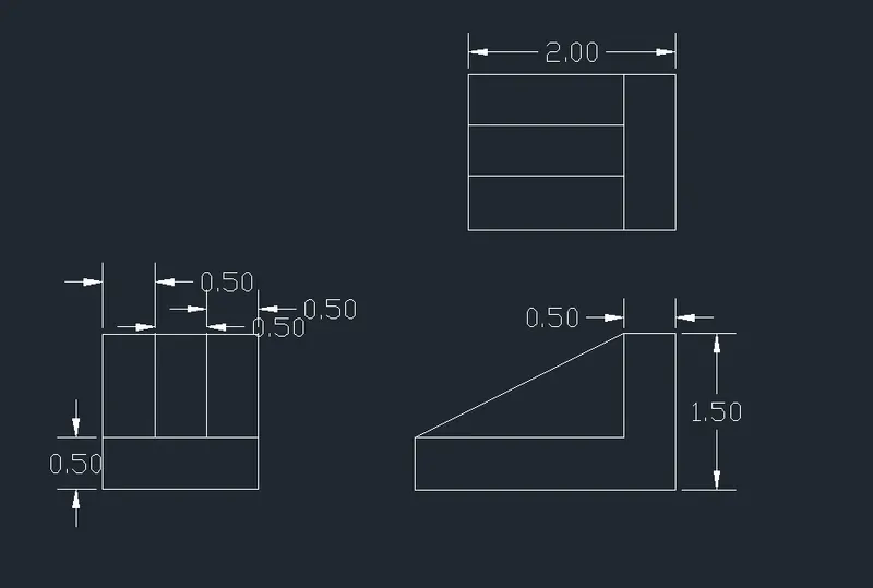
Procedure:- The fig. 6 can be drawn using line command and with the help of coordinate system as rectangular polar coordinate method which can efficiently create the desired geometry.
Get started with the autocad⮕go to utilities to setup the units ⮕enter
units⮕select decimal⮕with precision as 0.00⮕select angle in decimal degrees⮕with precision as 0⮕finish up with the units setting
use the line command⮕specify the first point⮕then,the coordinates used to draw the line geometry here is @(1.50<0)⮕take through offset of the 1.5 unit line on upper side⮕from the end point takecoordinate as @(1<90)⮕@(1.50<180)⮕close ⮕ take the offset of 1 unit line from the right till the left joint completed as shown in the geometry.⮕extend the 1.5 base line to right and extend the upper line also which is at a spacing of 0.5 from the base line ⮕from that end of upper line of base line take the coordinate as@(2<0) and @(1<90)⮕complete the triangle ⮕take the offset of the base and perpendicular of the triangle through 0.5 below and extend those lines by 0.5 on either direction⮕join them like in the question geometry.
extend the 1.50 unit perpendicular line to upper portion⮕then accordingly as in the question figure take @(2<180) ⮕@(1<270) ⮕close the geometry⮕take offset of 1.50 unit line through 0.5units ⮕join the lines so as to look alike in the shown figure.
now, the sketch is completed ⮕
select the annotation tool from the menu bar⮕modify it for change in scale factor so that dimensions on paper can be clearly visible⮕set the primary units and precision as set as per the unit settings oin utilities⮕choose dimlinear for marking the linear dimensions⮕choose dimangular to mark the angular dimensions.
Result:- The resultant image of the procedure followed is shown below,
7.for fig7.
Aim:- To draw the given geometry using Auto Cad.
Introduction:- Auto Cad is a computer aided drawing softaware which comes with a lot no of drawing tools and modification tools, and Auto Cad can be used to draft in 2D and in 3D as well.Auto Cad is developed by the company named as Autodesk,each year the company launches its upgraded version in the open market.As this software is very costly our project here is produced by the autodesk student version.
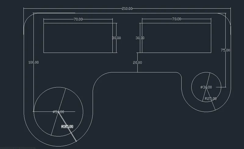
Procedure:- The fig. 7 can be drawn using line command and circle command with the help of coordinate system as rectangular polar coordinate method and arc command to draw respective shown arcs which can efficiently create the desired geometry.
Get started with the autocad⮕go to utilities to setup the units ⮕enter
units⮕select decimal⮕with precision as 0.00⮕select angle in decimal degrees⮕with precision as 0⮕finish up with the units setting
use the line command⮕the coordinates used to draw the line geometry here is @(210<180)⮕create a circle of 70 units with 100unit line end point as the tangent of the circle⮕using the center of 70 unit circle create a cicle of diameter 50 units at the bottom left portion of the geometry ⮕use the 70 unit diameter circle and draw a tangent line from the right side and extend it to the level of the 75 units from the top line of 210 units⮕draw an arc of 20 radius then extend it to right ⮕now, use the 70 unit diameter circle and draw a tangent line from the right side and extend it to the level of the 75 units from the top line of 210 units⮕draw an arc of 20 radius then extend it to right⮕create a circle of 60 units with 60 unit line end point as the tangent of the circle⮕using the center of 60 unit circle create a cicle of diameter 50 units at the bottom right portion of the geometry ⮕use the 60 unit diameter circle and draw a tangent line from the left side and extend it to the level of the 75 units from the top line of 210 units⮕create an arc there of and join as shown in the question figure.
use the fillet command(trim,radius) and fillet the corner of 210 unit line and 100 unit line at left side of upper portion,similarly do for the right portion for same radius.
now, the sketch is completed ⮕
select the annotation tool from the menu bar⮕modify it for change in scale factor so that dimensions on paper can be clearly visible⮕set the primary units and precision as set as per the unit settings oin utilities⮕choose dimlinear for marking the linear dimensions⮕choose dimangular to mark the angular dimensions.
Result:- The resultant image of the procedure followed is shown below,
8.for fig8.
Aim:- To draw the given geometry using Auto Cad.
Introduction:- Auto Cad is a computer aided drawing softaware which comes with a lot no of drawing tools and modification tools, and Auto Cad can be used to draft in 2D and in 3D as well.Auto Cad is developed by the company named as Autodesk,each year the company launches its upgraded version in the open market.As this software is very costly our project here is produced by the autodesk student version.
Procedure:- The fig. 8 can be drawn using cicle and arc command and wherever the dimensions are not mentioned use free hand joining and drawingv to make the figure lookalike as required to draw.
Get started with the autocad⮕go to utilities to setup the units ⮕enter
units⮕select decimal⮕with precision as 0.00⮕select angle in decimal degrees⮕with precision as 0⮕finish up with the units setting
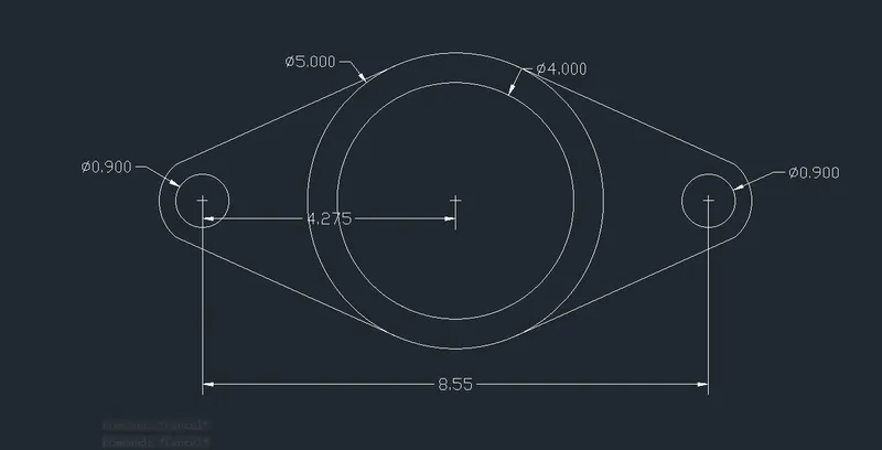
choose circle(center,diameter) ⮕specify the center anywhere in the drawing area and draw a circle with a diameter of 5 units and again using the same centre draw a circle for a diameter of 4 units,⮕from the same center point mark two points at a distance apart of 4.275 both the sides⮕the same points at both the ends will act as the center of the circle⮕with that center draw circles at both the sides by using circle(centre, diameter) of diameter 0.90 units.⮕using the same center aty both the ends draw a circle of 1.80 units ⮕trim of the undesired segments as per required in the question figure.⮕join the tangential line of 1.80 unit diameter circle 5 unit diameter circle at the upper and lower portion to look alike of the given figure.
now, the sketch is completed ⮕
select the annotation tool from the menu bar⮕modify it for change in scale factor so that dimensions on paper can be clearly visible⮕set the primary units and precision as set as per the unit settings oin utilities⮕choose dimlinear for marking the linear dimensions⮕choose dimangular to mark the angular dimensions.
Result:- The resultant image of the procedure followed is shown below,
9.for fig9.
Aim:- To draw the given geometry using Auto Cad.
Introduction:- Auto Cad is a computer aided drawing softaware which comes with a lot no of drawing tools and modification tools, and Auto Cad can be used to draft in 2D and in 3D as well.Auto Cad is developed by the company named as Autodesk,each year the company launches its upgraded version in the open market.As this software is very costly our project here is produced by the autodesk student version.
Procedure:- The fig. 8 can be drawn using cicle and arc command and wherever the dimensions are not mentioned use free hand joining and drawingv to make the figure lookalike as required to draw.
Get started with the autocad⮕go to utilities to setup the units ⮕enter
units⮕select engineering to give the input in feet and inches⮕with precision as 0'00''⮕select angle in decimal degrees⮕with precision as 0⮕finish up with the units setting
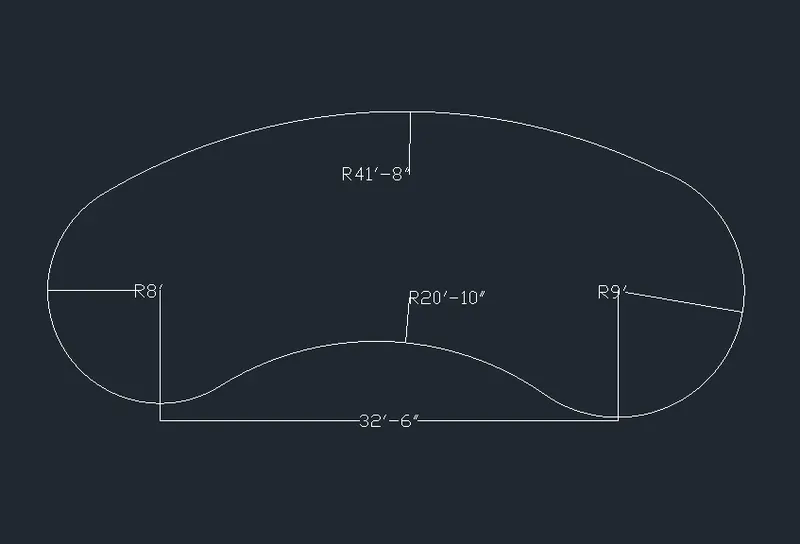
Mark two points at an apart of 32'6'' at both the ends⮕turn on the object snap for end point⮕both the ends acts as center of the circle⮕draw two circles one at left side for a dradius of 8'00'' and one at right side for a radius of 9'00''.
now,draw a circle using circle(Tan Tan rad)⮕ choose one tangent at below the 8'0'' circle and another tangent also below the 9'0'' circle then,give 20'10'' radius input⮕a circle will be created just below the two circles touching its tangent from the bottom.
now,again draw a circle using circle(Tan Tan rad)⮕ choose one tangent at top of the 8'0'' circle and another tangent also at top of the 9'0'' circle then,give 41'8'' as radius input⮕a circle will be created just touching the top points of both the end circles (or) just draw a circle of 41'8'' as radius anywhere in the drawing area and overlap it in such a way that it overlaps and it touches the top tangent points of both the end circles.
now, trim of the undesired segments by looking into the given fig, and hence the sketch is ready.
select the annotation tool from the menu bar⮕modify it for change in scale factor so that dimensions on paper can be clearly visible⮕set the primary units and precision as set as per the unit settings oin utilities⮕choose dimlinear for marking the linear dimensions⮕choose dimangular to mark the angular dimensions.
Result:- The resultant sketch of the procedure followed above is shown below
10.for fig10.
Aim:- To draw the given geometry using Auto Cad.
Introduction:- Auto Cad is a computer aided drawing softaware which comes with a lot no of drawing tools and modification tools, and Auto Cad can be used to draft in 2D and in 3D as well.Auto Cad is developed by the company named as Autodesk,each year the company launches its upgraded version in the open market.As this software is very costly our project here is produced by the autodesk student version.
Procedure:- The fig. 10 can be drawn using cicle and arc command and wherever the dimensions are not mentioned use free hand joining and drawingv to make the figure lookalike as required to draw.
Get started with the autocad⮕go to utilities to setup the units ⮕enter
⮕create a rectangle of any dimension but should look alike as in the given figure ⮕with same rectangle take through offset and create one more rectangle so that it enclosed the previous rectangle.
⮕create more rectangles in such a way that it just overlaps both the previous circle.
⮕select rotate tool⮕select the object that is both the rectangle at once here, the latest drawn rectangles will be selected and rotate them in such a way that it looks alike as in the given figureVtrim off the segments wherever shown in the given figure.
Now, the sketch is ready
Result:-The resultant sketch of the procedure followed above is shown below

11.for fig11.
Aim:- To draw the given geometry using Auto Cad.
Introduction:- Auto Cad is a computer aided drawing softaware which comes with a lot no of drawing tools and modification tools, and Auto Cad can be used to draft in 2D and in 3D as well.Auto Cad is developed by the company named as Autodesk,each year the company launches its upgraded version in the open market.As this software is very costly our project here is produced by the autodesk student version.
Procedure:- The fig. 11 can be drawn using line command and wherever the dimensions are not mentioned use free hand joining and drawingv to make the figure lookalike as required to draw.
Get started with the autocad⮕go to utilities to setup the units ⮕enter
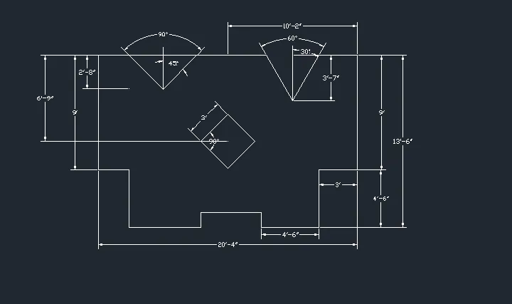
⮕choose the line command to draw the shown line geometry with coordinates as @(4'6''<0),@(4'6''<90), @(3<0), @(9<90),@(10'2''<180)⮕at half of the distance from the corner of right side⮕draw line of length as @(3'7<270)⮕from the bottom end of 3'7'' line draw a line at an angle of 60 deg and extend it to the top edge then again draw a line at an angle 120 deg from the same end point and extend it the face⮕trim off the line segments between those inclined lines⮕mark the angles between them and get checked with the given figure⮕now etend the 10'2'' line leftwards and mark the mid point of that line⮕from the mid point draw a line of @(2'8''<270)⮕from the bottom of that line draw a line t an angle of 45deg and extend it to the top edge then again draw a line at an angle 135deg from the same end point and extend it the face⮕trim off the line segments between those inclined lines⮕mark the angles between them and get checked with the given figure⮕from the left end of 10'2'' line draw a line with the coordinate as @(6'9''<270) ⮕now locate the centre to draw the square of length 3' at an angle of 45 deg from the x-axis ⮕join the left segments as shown in the given figure ⮕match with the given figure.
hence,the sketch is ready,
Result:-The resultant sketch of the procedure followed above is shown below