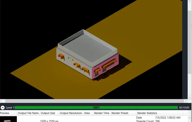
Project 2_Creating a 3D rendered model for a Residential Building in AutoCad
Create a 3 dimensional model of the residential building with a rendered view.
Aim:- To create a complete building model right from 2D planning layout to 3D modelling.
Procedure:-
Step 1--
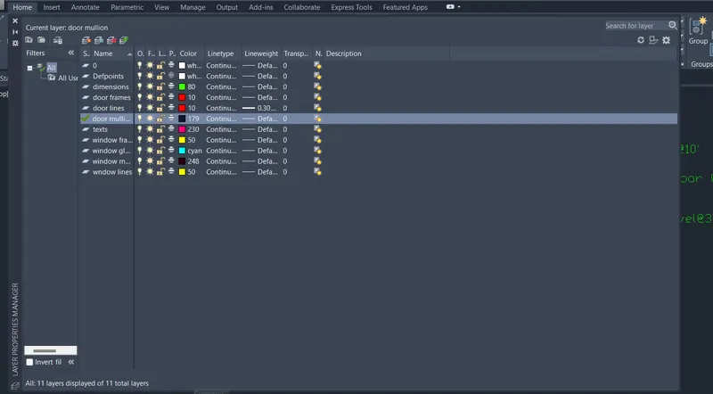
Creating layers:-
- Start with the autocad⮕ set the unit type as Engineering with the precision 0'0'' and the insertion unit as inches⮕analyse the screen required for the drawing and set the screen size using limmax⮕Zoom⮕ all⮕ now the screen is ready for the drawing.
- create the different layers in the name of expected different components of the drawing.
- The layers can be such that the wall layer,window, door,dimensions,texts,the layers are provided to work in 3D also and the names for those layers are designated with 3D as initial.
- Change the color and other features available in the layer option for the distinct vision of each component.
- The snap of the layer is as follows.
Step 2:-- Creation of the 2D plan layout.
- Switch the workspace to 3D basics and keep the screen in top view.
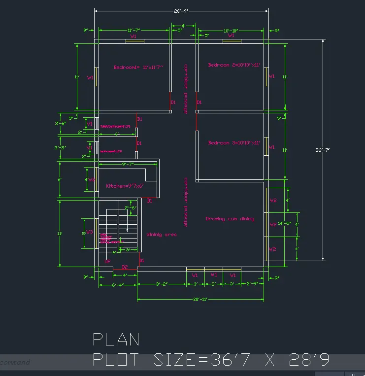
- First of all the planning of the building is carried in such a way that it involves the arrangements of bedrooms,toilet/bathrooms,kitchen,hall and other building components.
- The layout of the plan is done in 2D using drawing tools like line tool,rectangle etc and modifying tools such as fillet,trim,extend etc.
- The dimensions are marked and the required texts are provided as well.
- The snap for the same is as follows.
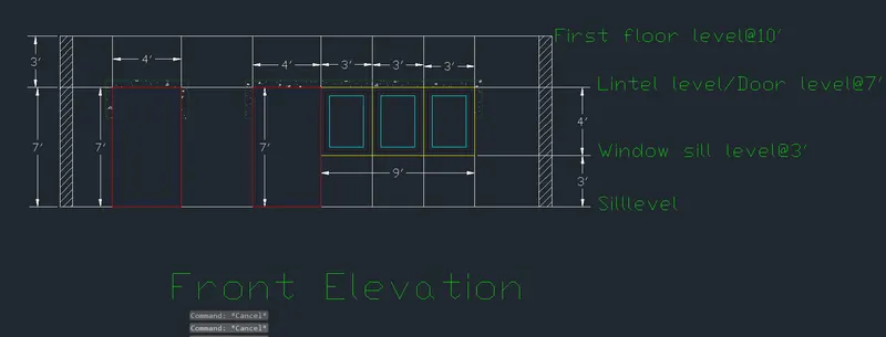
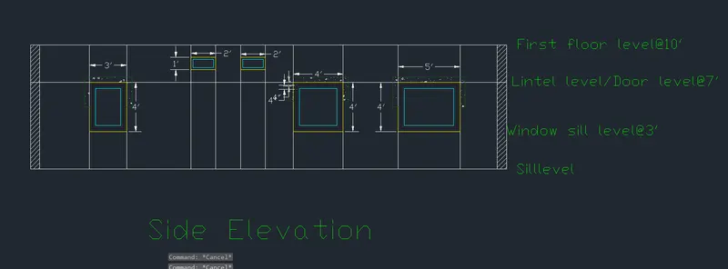
Step 3:-- Creation of the front elevation and side elevation of the drawn plan layout.
- using xline(ver) mark the lines corresponding to the lines in plan in vertical direction.
- Take offset from the sill level for different levels like,window sill,lintel/door level,floor level etc.
- Trim off the unwanted lines to create the openings like door,winows ,ventilators etc.
- Mark the dimensions and the texts as per requirement.
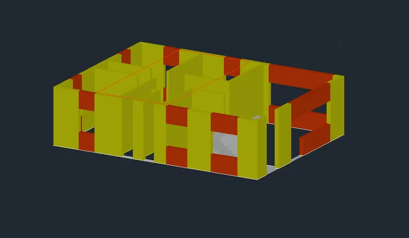
Step 4:-- Creation of the 3D wall.
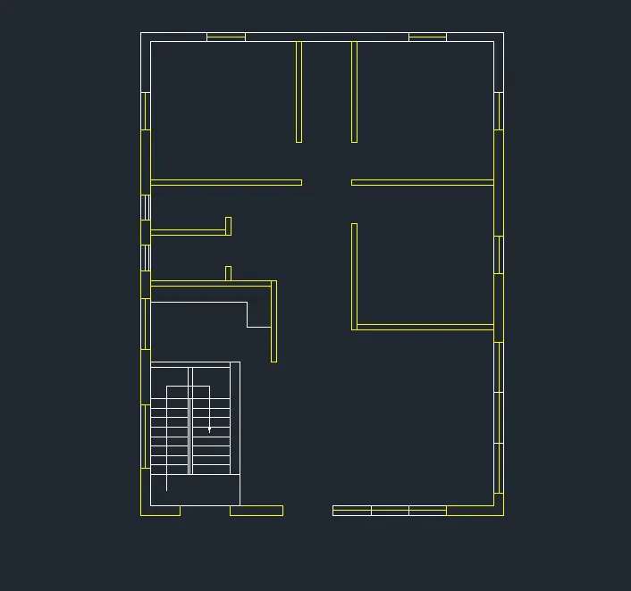
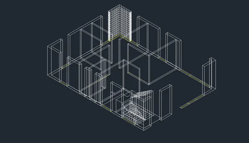
- To create the 3D walls it is required to create regions where the wall sections will be.
- The regions can only be created for closed loops so,create close loops using rectangle and polyline.
- After creating the regions switch the view mode into 3D basics.
- In 3D basics select all the regions at once for the wall and extrude it to 10' in z direction.
- Leaving the space for wall and windows wall is extruded to the first floor level.
- use union to all the walls extruded.
- The snap for the same is as follows.
Step 5:-- Creation of door and windows.
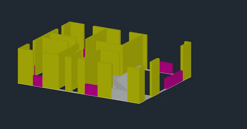
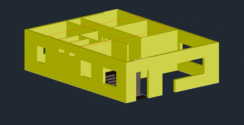
- To create the door and windows ⮕ First create regions for the same.
- After creating the regions select all the windows first and extrude it to 3' that is window sill level.
- Now,take the ucs command control on the top of the wall so that wall portion in window sections from lintel level can be extruded.
- create rectangles in each of the window sections and extrude it in negative z direction upto the lintel level.
- Give different colors to distinguish between the components.
- select all the wall portions coming under and over the window section and make union of it.
- Similarly create the doors from sill level to lintel level.
- The snap for the same are as follows.
Step 6:-- Creation of the Front and Side elevation.
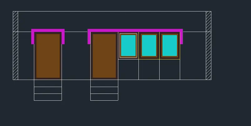
- To create the components of elements in 3D of the front elevation use the 2D plan drawn.
- use rotate 3D command and rotate the plan in z direction and paste the same on 3D elevation model in the right view.
- Use rectangle,create region,substract to make the individual components of windos and doors.
- Copy the elevation 2D plan tythat is rotated in 3d and create the windows components such as frames,mullions,glass etc.
- Similarly create the components for door also.
- Give the basic colours to the components to visualise them as a real material.
- Do the same for the side elevation.
- Create the regions for the sunshades and extrude as required.
- Snaps of this steps are as follows.
Step 7:-- Providing materials to different components to the 3D model.
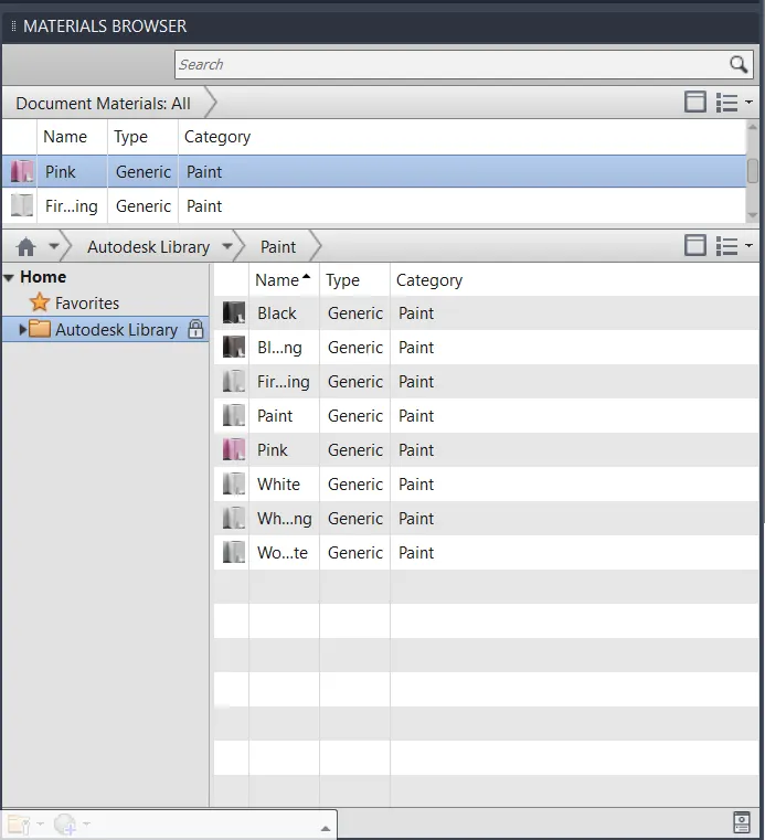
- To provide the materials from the library it is called material attach.
- To attach the materials first add the materials from the autodesk library for that use RMAT as the command⮕choose and add the required material and use option to assign to the selected components to attach the material with the model.
- Trying with the different materials and choose the suitable one .
- The snaps of the process are as follows.
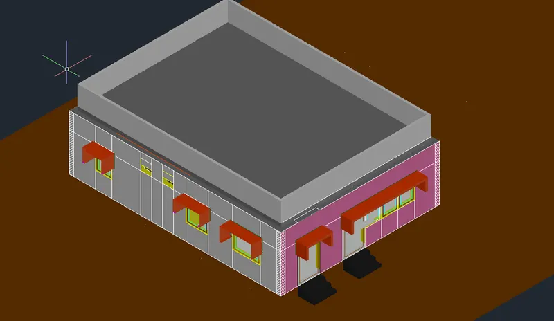
Step 8:-- Rendering of the created model.
- To render the 3D model first create different views by using the camera option or create new view option.
- Select the view go to render window and provide the settings and adjustkments in shadows, lights and environment.
- Give command RR the rendering algorithm automatically starts working and can be viewd in different tab created from rendering itself.
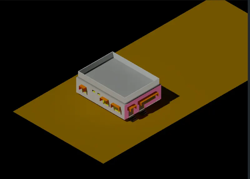
- The level of rendering decides how much time will it take complete while there are different levels of rendering available,some of them are like low level which takes the minimal time,coffee break quality ,it takes 10 minutes but the quality is good .some of the levels of rendering takes more than 12 hrs also.
- The snap of the coffee break quality level of rendering is as follows.
Results:-
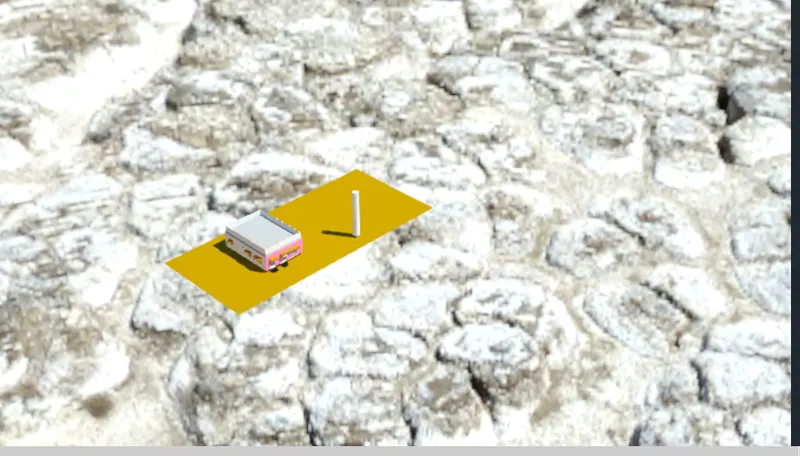
The finally rendered view of the 3D model is as follows.