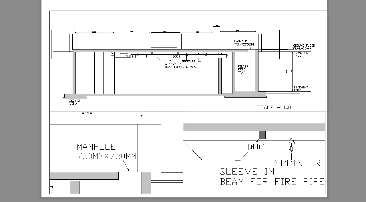
Creation of Multiple viewports, Scaling the drawing and setting in Template in AutoCad
1. Create a layout of the Plan and Section A of the project in Challenges 7, using the template Tutorial-mArch.dwt in a scale as given in the Figure. Use the MV command to create the viewport of the size as shown in Figure. Also, use ATTEDIT command to edit the information in the title block. Use A1 size for the layout. Take a plot.
Aim:-To create a layout of the pla and section of the project done in challenge 7.
Introduction:-
Model Space:- The model space is nothing but the screen of the autocad where all the drawings are performed available at the lower left corner.
viewports:- This is nothing but to split the screen in multiple views to work independently inside them.
Layout Space:- The space to layout the drawing for the documentation and to create multiple viewports,the various inbuilt templates are available to load into the layout and the drawing can be taken into required scale.
Procedure:-
- Start with the autocad⮕Here as directed in the question drawing is not needed to perform but to callout the previous drawings performed in challenges to create multiple viewports in layout in a given template.
- Callout the drawing/floor plan drawn in challenge 7.
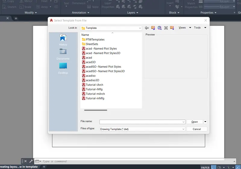
- Create a new layout page from the bottom left corner⮕rename it with any of your desired file name⮕right click on the layout page ⮕go to template⮕callout the inbuilt template Tutorial-mArch.dwt s directed in the question.
- Now,use the command "MV" to create the viewport in the layout⮕ the default viewport will be visible⮕delete the default view⮕creating the required rectangular section viewport ⮕use "MS" to zoom in and zoom out inside the drawing in viewport ⮕use "PS" to zoom -in or zoom-out the sheet of the layout and scale the drawing as directed in the question take the required view and using "PAN" ⮕complete the job for first view ⮕again use mv to create the new viewport in the same lasyout ⮕scale the drawing and take the desired view.
- using the snipping tool take the screenshot of the layout.
Results:- The snap of the layout are as follows:-
choosing the the inbuilt template Tutorial-mArch.dwt
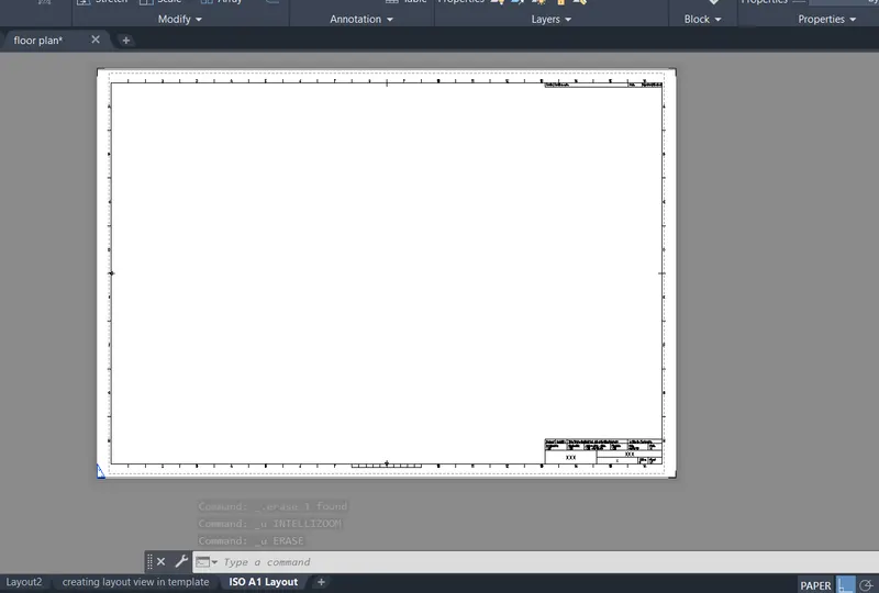
creating view in model space
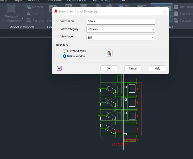
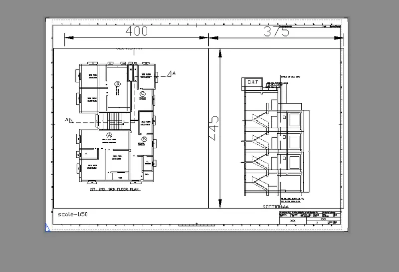
creating view in layout space
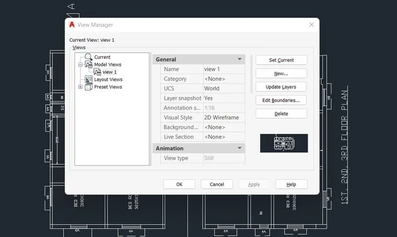
The final viewports of the drawing,
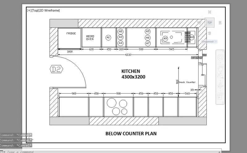
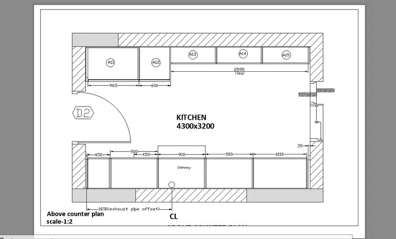
2. Create a layout of the Kitchen drawn in Challenge 9 as shown in Figure. Use the scale as shown in the Figure. Use A4 Size page for the layout. Take a plot.
Aim:-To create a layout of the kitchen layout plan of the project done in challenge 9.
Introduction:-
Model Space:- The model space is nothing but the screen of the autocad where all the drawings are performed available at the lower left corner.
viewports:- This is nothing but to split the screen in multiple views to work independently inside them.
Layout Space:- The space to layout the drawing for the documentation and to create multiple viewports,the various inbuilt templates are available to load into the layout and the drawing can be taken into required scale.
Procedure:-
- Start with the autocad⮕Here as directed in the question drawing is not needed to perform but to callout the previous drawings performed in challenges to create multiple viewports in layout in a given template.
- Callout the drawing/floor plan drawn in challenge 7.
- Create a new layout page from the bottom left corner⮕rename it with any of your desired file name⮕right click on the layout page ⮕go to page setup manager and choose the A4 paper as directed in the question.
- Now,use the command "MV" to create the viewport in the layout⮕ the default viewport will be visible⮕delete the default view⮕creating the required rectangular section viewport ⮕use "MS" to zoom in and zoom out inside the drawing in viewport ⮕use "PS" to zoom -in or zoom-out the sheet of the layout and scale the drawing as directed in the question take the required view and using "PAN" ⮕complete the job for first view ⮕again use mv to create the new viewport in the same lasyout ⮕scale the drawing and take the desired view.
- using the snipping tool take the screenshot of the layout.
Results:- The snap of the layout are as follows:-
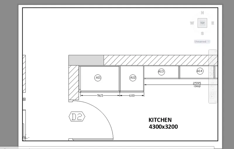
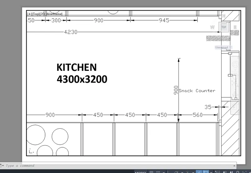
3. Create a layout of the section created in Challenges 9.
Use scale as mentioned in the Figure. Use MV command create multiple viewports. Take a plot.
Aim:-To create multiple viewports in layout of the section of the industrial building performed in challenge 9.
Introduction:-
Model Space:- The model space is nothing but the screen of the autocad where all the drawings are performed available at the lower left corner.
viewports:- This is nothing but to split the screen in multiple views to work independently inside them.
Layout Space:- The space to layout the drawing for the documentation and to create multiple viewports,the various inbuilt templates are available to load into the layout and the drawing can be taken into required scale.
Procedure:-
- Start with the autocad⮕Here as directed in the question drawing is not needed to perform but to callout the previous drawings performed in challenges to create multiple viewports in layout in a given template.
- Callout the drawing/floor plan drawn in challenge 7.
- Create a new layout page from the bottom left corner⮕rename it with any of your desired file name⮕right click on the layout page ⮕go to page setup manager and choose the A4 paper as directed in the question.
- Now,use the command "MV" to create the viewport in the layout⮕ the default viewport will be visible⮕delete the default view⮕creating the required rectangular section viewport ⮕use "MS" to zoom in and zoom out inside the drawing in viewport ⮕use "PS" to zoom -in or zoom-out the sheet of the layout and scale the drawing as directed in the question take the required view and using "PAN" ⮕complete the job for first view ⮕again use mv to create the new viewport in the same lasyout ⮕scale the drawing and take the desired view.
- using the snipping tool take the screenshot of the layout.
Results:- The snap of the layout are as follows:-