Introduction to REVIT concepts
Aim:- To perform the activities using Revit software as directed in the question.
1) From the file menu, create a new project (Structural / Architectural / Construction template ) and name the project appropriately
Stepwise procedure is as follows:-
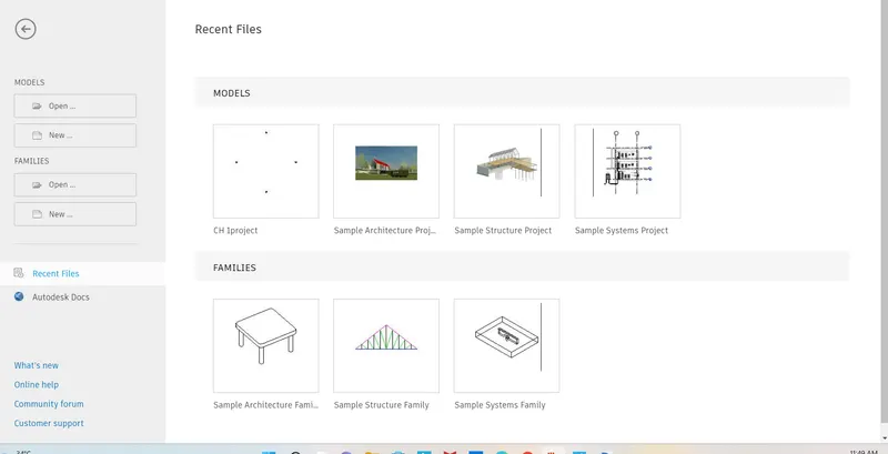
- Get start with rhe revit software
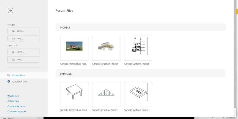
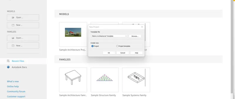
- Go to file menu to open for a new file⮕selecting the template as metric-architectural template.
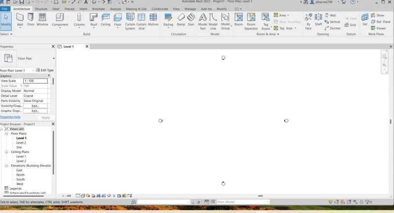
- After vselecting the template we get into the drawing screen.
- Now,save the project in the required destination folder with any name of your choice.
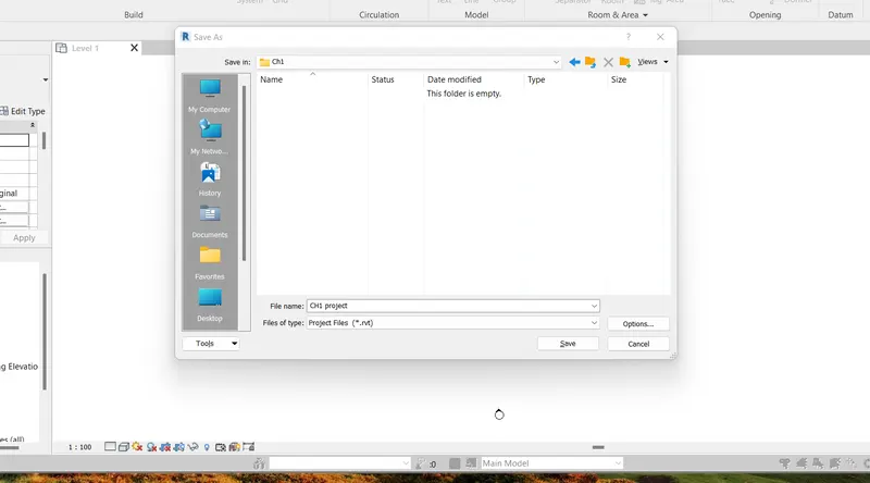
2) Save the new project file. Close and open using icons from file toolbar
Stepwise procedure is as follows:-
- Get start with rhe revit software
- Saving the new proiject file.
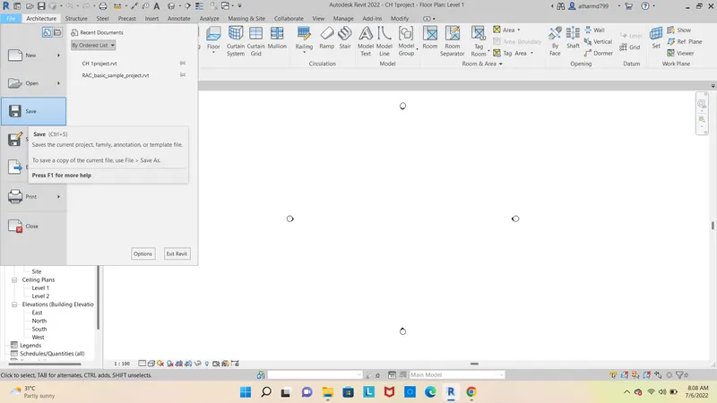
- Closing the new project file.
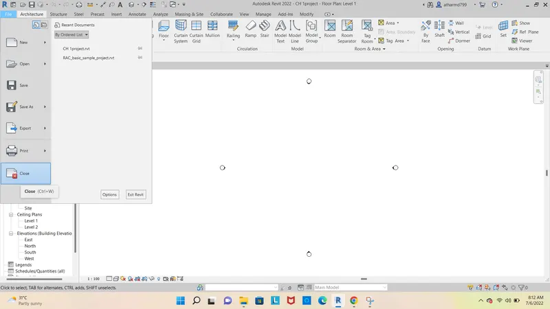
- Get over to the file menu and open the saved drawing file.
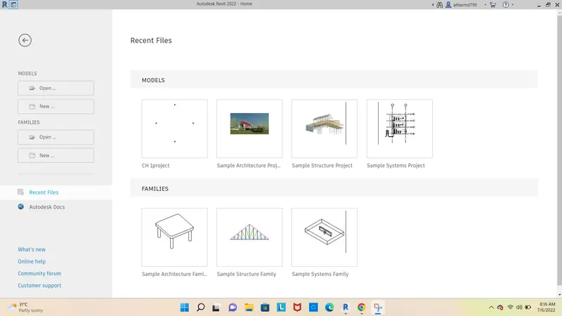
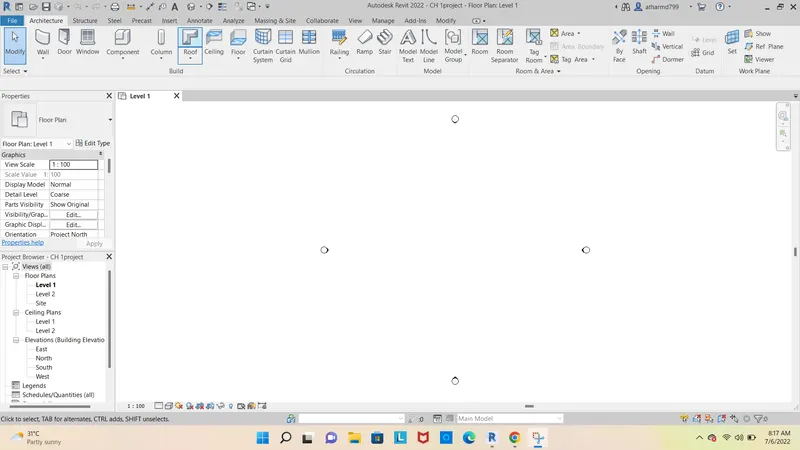
- Opening the project from file menu and get over to the drawing model space.
3) From the architecture/ structure toolbar familiarize with options to draw a wall. Create a rectangular layout of walls of about 40’-0” X 35’-0”
Stepwise procedure is as follows:-
- Get start with rhe revit software
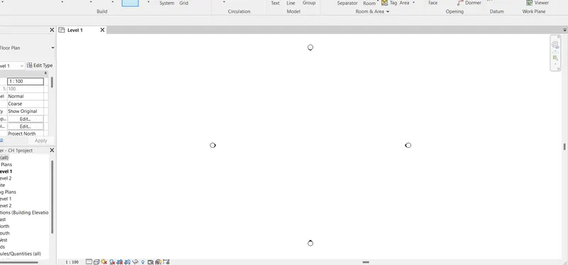
- Getting start with the revit model space.
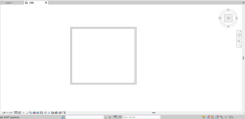
- Creation of walls in the model space by selecting the wall from architecture menu⮕selecting line for creation of walls⮕Start drawing the wall with the dimensions as directed in the question.
4) From the Annotate toolbar use the aligned option to add dimensions to the layout.
Stepwise procedure is as follows:-
- Get start with rhe revit software
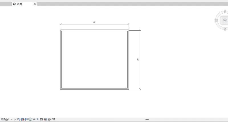
- Mark the annotations by selecting the annotation ⮕ linear or aligned from menu bar for the layout created just before.
5) Use the properties browser to switch to different wall types.
Stepwise procedure is as follows:-
- Get start with rhe revit software
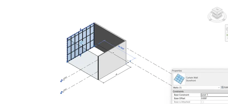
- Opening the project file drawn last⮕select the wall drawn in model space⮕The selected wall properties will reflect in the properties toolbar⮕switch the wall types from the drop down menu in which different wall types are available.
- The snap of the switching of all the four side drawn walls into a new type in 3D view is as follows.
6) Create a 3D view from the view toolbar and save the view with the appropriate name.
Stepwise procedure is as follows:-
- Get start with rhe revit software
- Opening the project drawn for the last question⮕Switching the mopdel space mode from 2D to 3D.
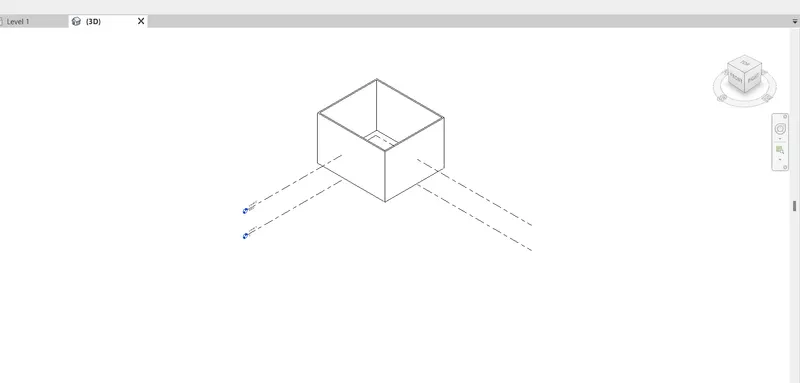
- Hover the mouse on the 3D view cube and rotate the view cube for the desired view you want, right click on the corner of the view cube ⮕ Select the option for save view and saving the view with any appropriate name.
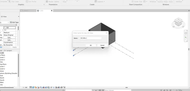
7) Navigate through the 3D model using the view cube. Orbit/pan through the model layout created.
Stepwise procedure is as follows:-
- Get start with rhe revit software
- Opening the project drawn for the last question⮕Switching the mopdel space mode from 2D to 3D.
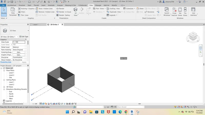
- Look for the navigation bar in the model space,if it is not on the screen ⮕ Go to view and from user interface drop down menu check for the navigation bar⮕ from the navigation bar select full navigation wheel⮕ There we got option for like orbit/pan⮕ using the orbit we can navigate the model in 360 degrees rotation.
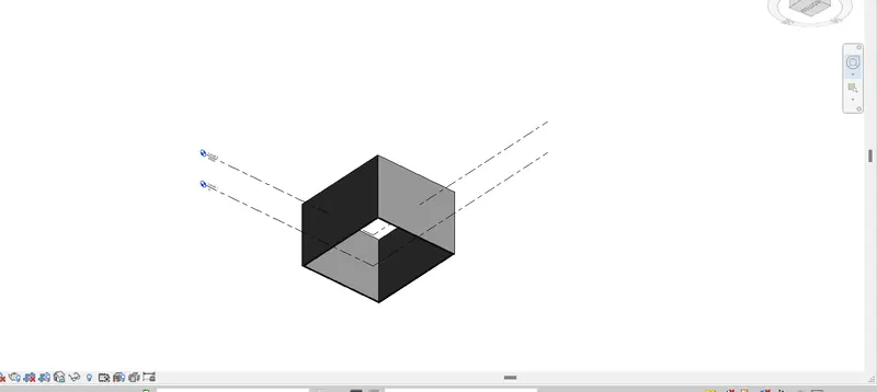
- The pan tool is used in revit to slide the model from right to left or in up and down without changing the view in model space, i.e, to just adjust the view on the model space.
8) Use the visibility settings option below to switch model to shaded, realistic, hidden lines options.
Stepwise procedure is as follows:-
- Get start with rhe revit software
- Opening the project drawn for the last question⮕Switching the mopdel space mode from 2D to 3D.
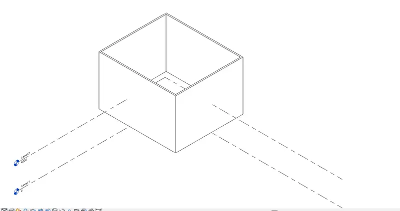
- Go to the bottom toolbar ⮕the cuboid shaped button herein allows to change the visual styles,
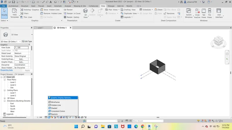
- Changing the visual style into shaded from wireframe is as follows,
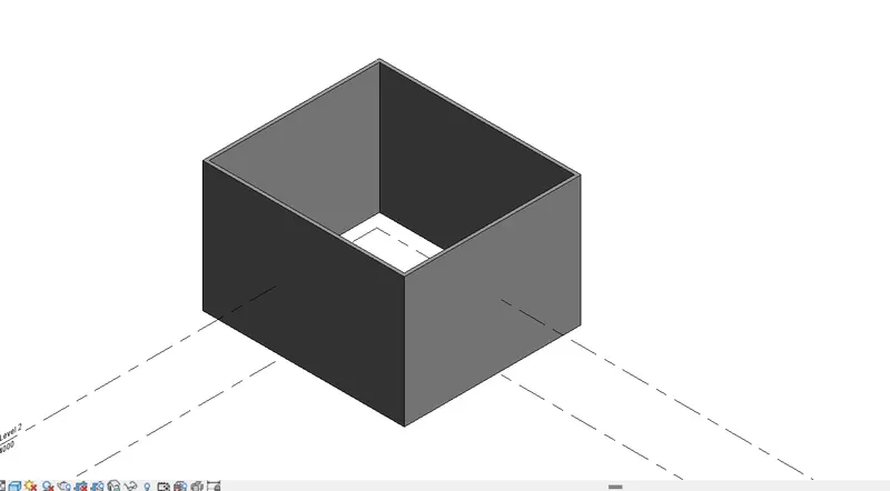
- Changing the visual style into wireframe from shaded is as follows,
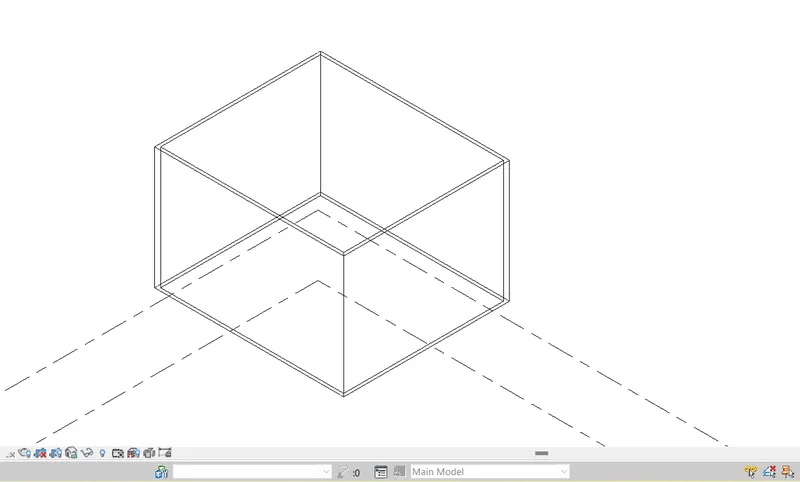
- Changing the visual style into hidden from wireframe is as follows,
9) Turn the sun path on and off to view shadings in the layout created.
- In the bottom toolbar⮕Hover over the various icons, there is one icon available for sunpath⮕click over that to turn on the sun path option ⮕it will ask either you want to make any changes like time,location,date or you want to go with the current settings ⮕here, we go for tghe current settings⮕The snap of the model with the sun path turned on is as follows
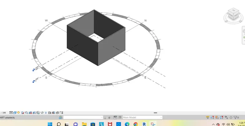
- Similarly get turned off with the sunpath then the snap of the same is as follows.
10) Use the Manage toolbar to enter project settings, project name, and project issue date (choose according to your convenience).
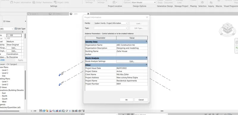
- To provide the information into the project⮕Go to manage toolbar under that project information icon is available,by selecting that icon a dialogue box will get open where we can provide the various information as per our convenience. The snap with the edited project information is as follows.
11) What is the Analyze toolbar used in Revit? How it is beneficial for design and modeling.
The analyze toolbar used in revit allows to perform analysis of the structure model created in 3D.There are various dimensional analysis available in revit analysis tab such as to analyze boundary conditions,loads,system analysis and also we can introduce load cases and load combinations in our 3d model Structure.
It is benificial in such a way that it provides the analytical measurements of the sustainability of the model we created,It measures the energy optimization of the building that we are going to create as it performs an analytical energy analysis of the structure model by considering the types of building materials that will be used in the actual construction process. In that way we can asses that whats the impact will be on environment and natural resources due to the particular structure.
12) What are the links that Revit supports to be linked to the model?
In the insert toolbar there are various options are available to link revit which are explained in details are as follows:-
- Link Revit-This option is used to link with the models of the structure which may be lying in the same campus of location and this option also establish the coordination between various disciplines of work such as architectural,Engineering,electrical.
- Link IFC- This option is used to refrence the information when once the project model gets revised it reflect the updated information if it is IFC linked.
- Link Cad-This option is used to link the 2D cad file to the current revit project.
- Link topography-This option is used to link the topography that is created through the civil 3D software to the structure modelled in revit.
13) Why do you need the Collaborate tab in Revit? How it supports modeling and its efficiency.
It is so important that a dedicated collaborate toolbar is available in the revit,it helps or supports the modelling and its efficiency in the way that is explained are as follows,
- It helps to establish the coordination between various disciplines of works on the project such as structure,architecture,mechanical and electrical.
- It allows various teams at different locations to work on a single project on cloud file.
- It allows only the assigned team to make any changes in the project.