Foundation Design using SAFE
1. Model the isolated footing provided in week 11 challenge on SAFE. Analyze and design it to verify the size, depth and steel provided as per calculations.
Aim:- To analyze and design it to verify the size, depth and steel provided as per calculations for the model of isolated footing provided in week 11 challenge using safe.
Procedure:-
Required Data for Design and Analysis:-
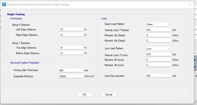
Unfactored load=2000/1.5=1333.3 kn.
dead load Breakup=1333.3/2=666.7Kn. Let's adopt 675Kn.
Live load breakup= 1333.3/2=666.7Kn. Let's adopt 675Kn.
Subgrade Modulus of Soil =(Safe Bearing CapacityXFactor to Safety /maximum settlement)
Maximum settlement allowed=50mm
So, We have =150X3/0.05=9000Kn/m^3
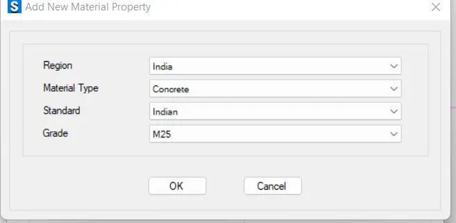
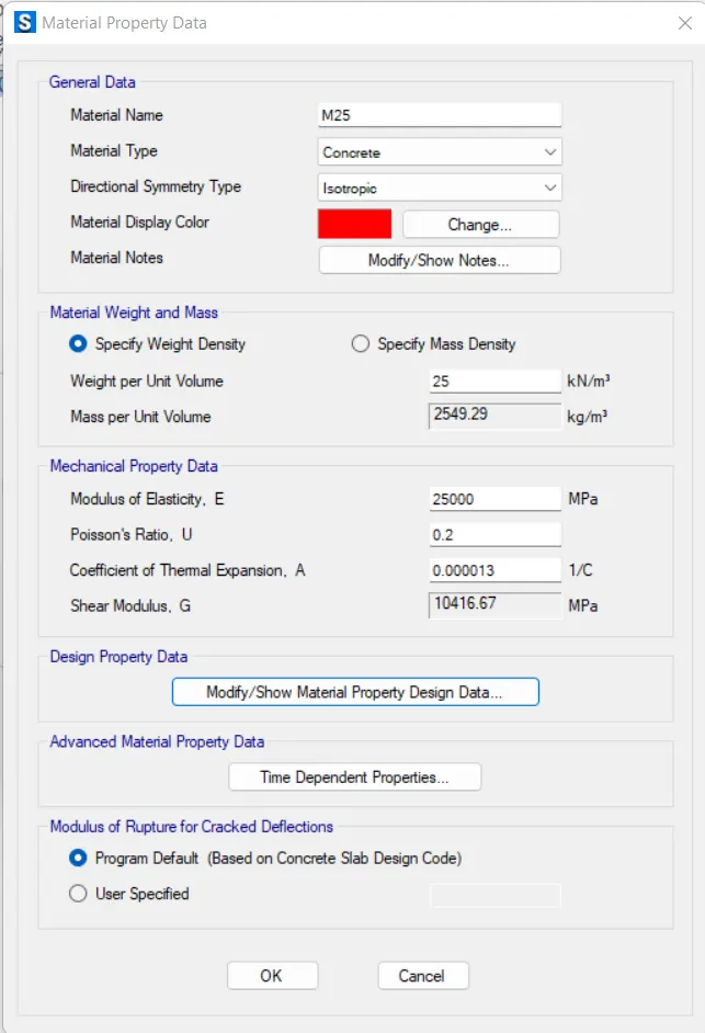
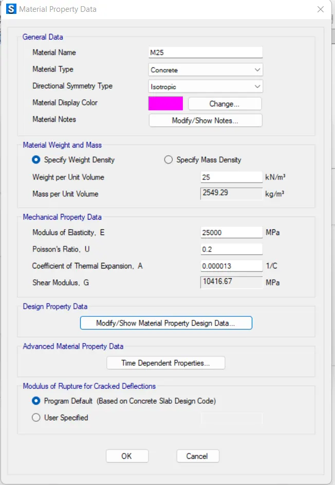
- Modulus of Elasticity of M25 concrete=5000√Fck=5000√25=25000 N/mm^2
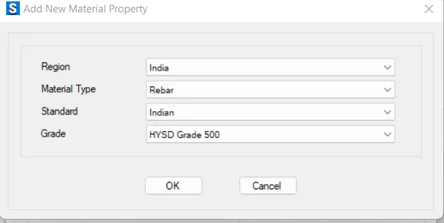
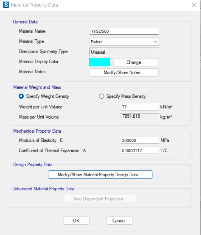
- Rebar yield strength(Fy)=500N/mm^2
- Rebar ultimate strength=575N/mm^2
Start Modelling in the Safe Software
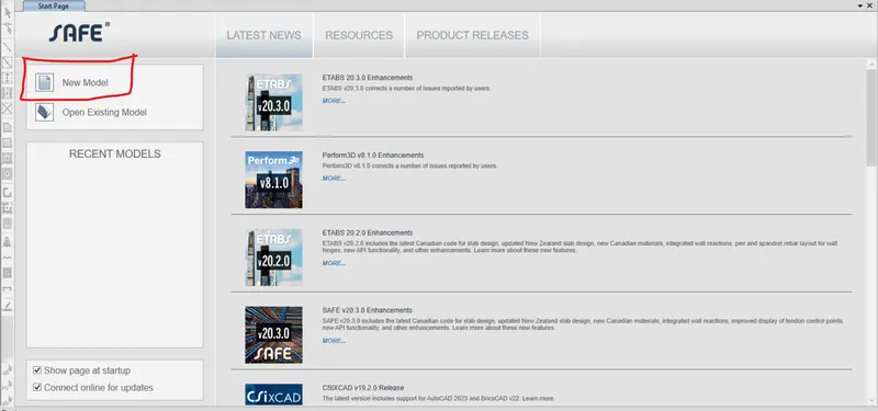
- Start with the SAFE Software and find the option for creating new model.
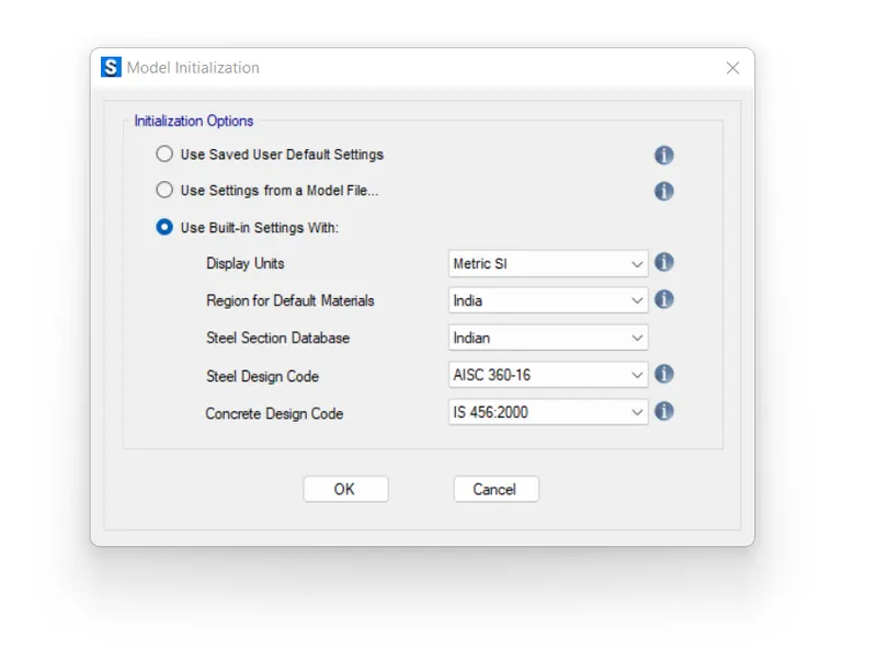
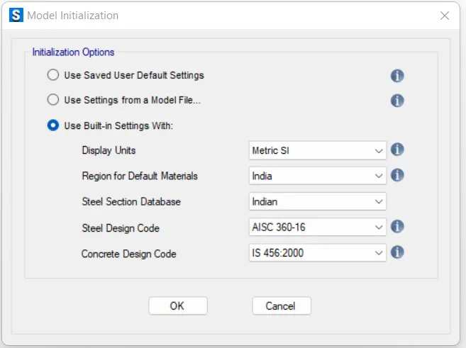
- Now the model initialization page will get open,select the desired units and code of practice and other options suitably.
- Select the Isolated footing option from this Tab
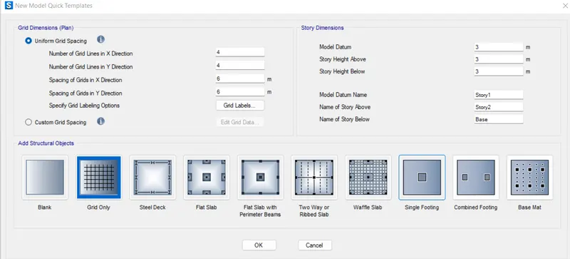
- Defining the structural geometry and properties of the isolated footing.
- Now, Define Material properties-
Go to Define tab under which choose material properties
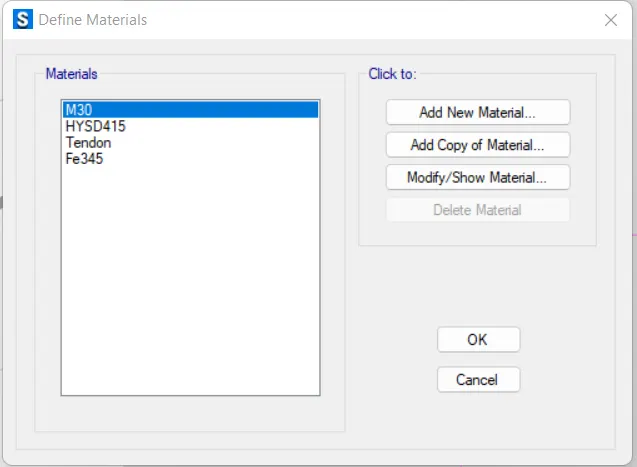
- Defining the rebar properties.
- Defining the concrete material properties,
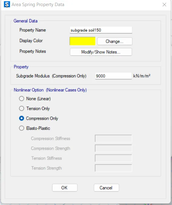
- Define the subgrade soil property.
About the soil the important point needs to be kept in mind is that here the soil is modelled by considering it as a spring so that it is required to feed the subgrade modulus which is nothing but a kind of spring constant can be called.
Subgrade Modulus of Soil =(Safe Bearing CapacityXFactor to Safety /maximum settlement)
Maximum settlement allowed=50mm
So, We have =150X3/0.05=9000Kn/m^3
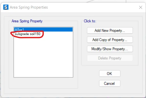
Go to define under which choose Spring properties⮕Area springs⮕in the tab gets opened it is defined as follows,
- Now, Define Section properties,
- Here, for the foundation design the section properties is defined for slab
- Go to define tab under which choose section properties then,select slab sections
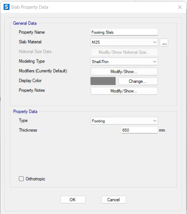
- Click to add new property⮕Give name ⮕and define other required inputs like thickness of slab,grade of concrete to be used.
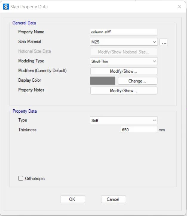
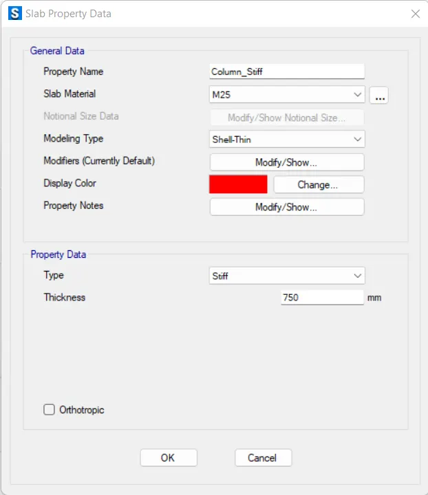
- Define another property, the area within the slab under which the column will rest and given its name as column stiff, and the type selected will also be stiff while thickness and all will remain be the same.
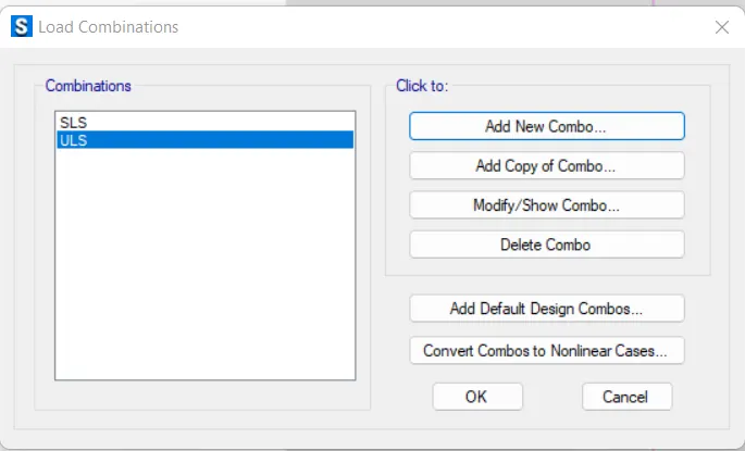
- Now,Define the Load combinations.
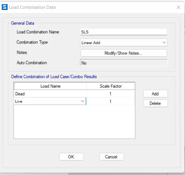
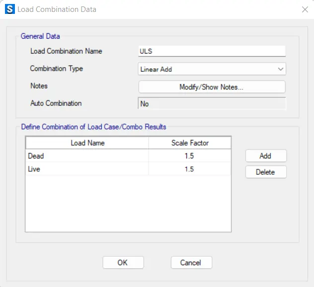
- Here, in the design of foundation two types of load combinations are defined.
- one is ultimate limit state for the dead and live load combination as (1.0DL+1.0LL)
- Another one is for ulimate limit state in which a factor of 1.5 is multiplied as (1.5DL+1.5LL)
- Defining for both is depicted as below,
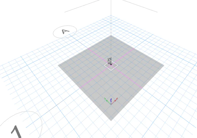
Now, Assigning the loads to the model.
- As we know that we have already assigned the load at the model initialization step only.
- Here, in this step our motive is to verify that they are assigned properly or not.
- For thios Go to display tab under which choose Show load assign then from the opened tab check for dead and live load assignment.
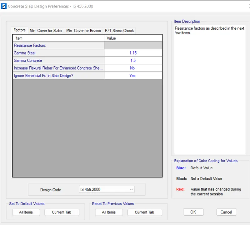
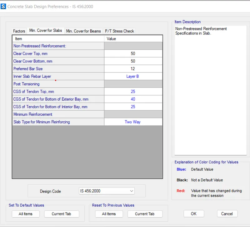
- Now, Check for the design parameters
Go to Design tab under which choose concrete slab/beam design and then choose view design preferences
- Now,choose which are the design combinations that will be run
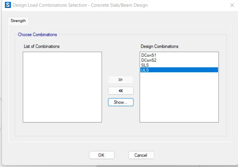
- Now, the model is ready to perform the analysis
Use the play button available above the model space to perform the analysis of the model,
After the analysis the model reflected in the model space as,
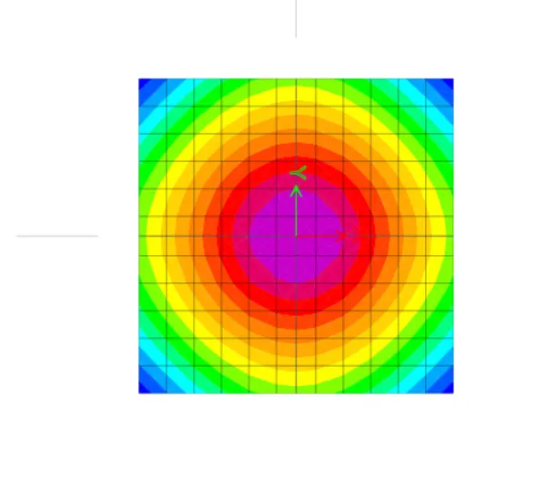
- Once the analysis is done there are three things which primarily needs to check.
- Displacement under load combination,
The displacement for load combination SLS is found to be under control as it within 10mm and the limit is for 50mm.
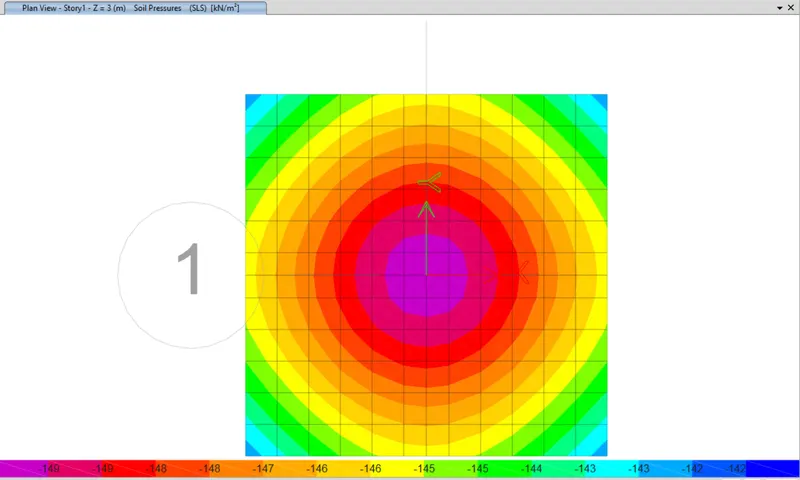
2. Bearing Pressure
Go to Display then choose show force stress diagrams then select for reactions, select to check for combinations
This parameter is also under control as it is found to be within limit as the limit is that it should no go beyond 150 Kn/m2.
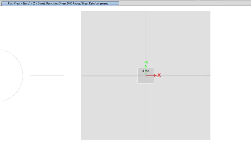
3.Punching Shear
It also passes the parameter for punching shear as the value is found to be lesser than 1 if it is found to be more than 1 then it will be considered as to be failed in punching shear criteria
- For extracting the reinforcement details here we are required to add design strips first,
- So, First unlock the model then go to edit and under which choose add/edit design strips.
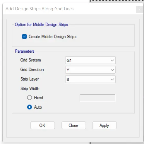
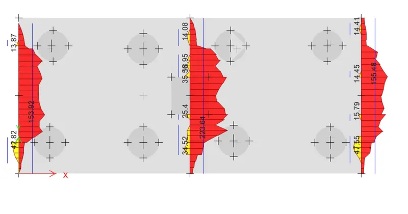
- Now, we can look into the reinforcement details-
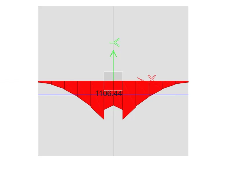
- Maximum rebar area for the strip A
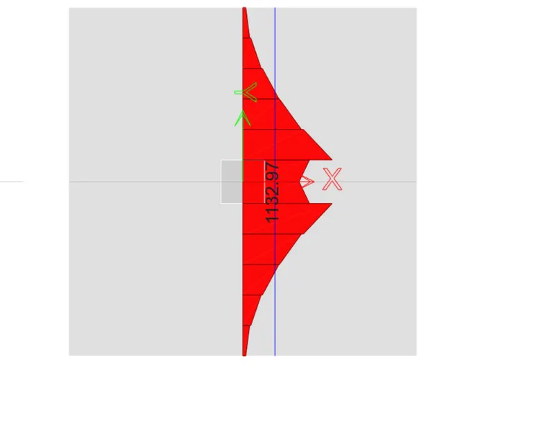
- Maximum rebar area for the strip B
2. A column of size 600x600 carrying an unfactored gravity load (DL+LL) of 1175 KN is to be supported on pile cap, which ultimately transfers load to the piles underneath. Piles of 16 metres length and 500 mm diameter are to be used. Each pile has a load carrying capacity of 200 KN. Model, analyse and design the pile cap on SAFE to evaluate the following:
- Pile group to be used
- Depth of pile cap
- Longitudinal steel on top and bottom face in both directions
Aim- To analyze and design the pile cap for the given size of column and for the given loadsing conditions.
Procedure:-
- Data required for SAFE analysis and design.
Given Data
Column size= 600 x 600 sq.m
Unfactored Gravity load = 1175 KN
Length of the pile to be used = 16 meters
Diameter of one pile = 500 mm
Pile Bearing Capacity = 200KN
Preliminary calculations
Unfactoreed load=1175 Kn.
Dead load Breakup=1175/2=587.5 Kn.
Live load Breakup=1175/2=587.5 Kn.
Point Spring of Pile= A X E /L=
area of one pile=(πxd^2)/4=(πx500^2)/4=196349.5 mm^2
E=5000 X Fck^0.5=5000x25^0.5=25000N/mm2
L=16000
Point Spring of Pile= A X E /L=196349.5X25000/16000=306796 N/mm
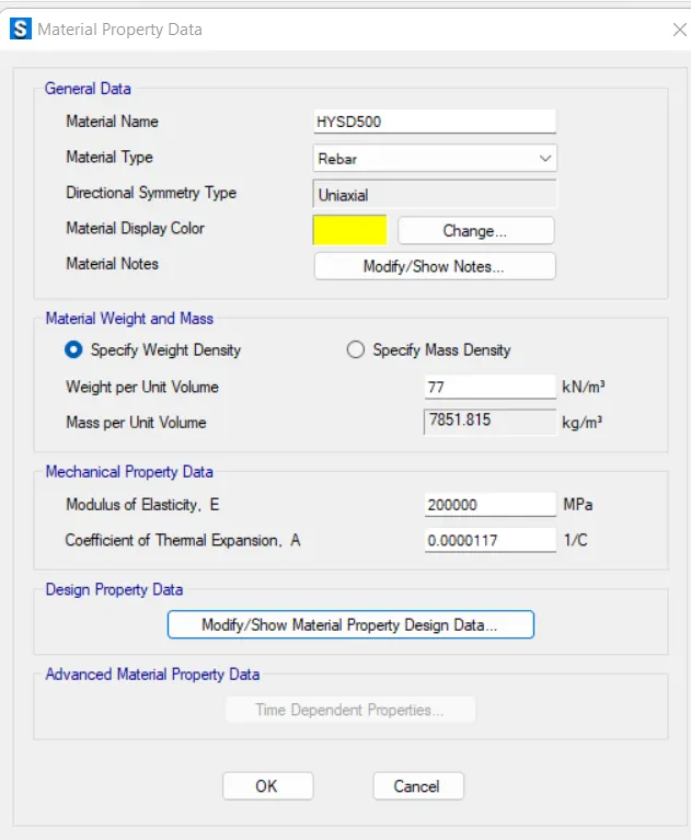
- Rebar yield strength(Fy)=500 N/mm^2
- Rebar ultimate strength=575 N/mm^2
- Elastic modulus of M25 concrete= 25000 N/mm^2
Number of piles required= unfactored load with self weight addition/individual pile capacity=1175X1.1/200=6.5 Nos.
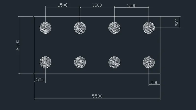
To distribute evenly, Let's consider 8 piles for symmetric placement of piles under pile cap.
- Considering C/C distance between piles=3 X pile diameter=3x500=1500mm
- Edge distance from pile center= 1 X pile diameter=1X500=500mm.
- Assume pile cap depth=500mm.
Assembly of the pile cap from the data obtained from calculations is as follows,
- Start modelling in the Safe software,
- Click to start with the new model and the model initialization is as follows,
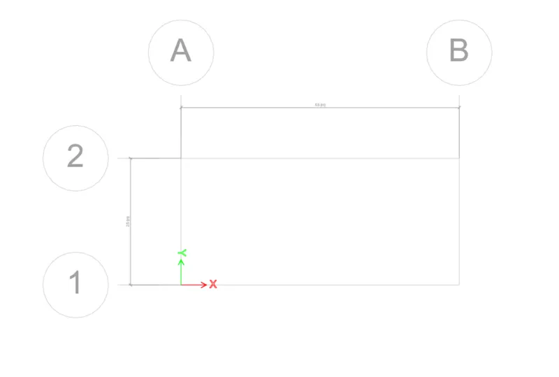
- Defining the grid pattern
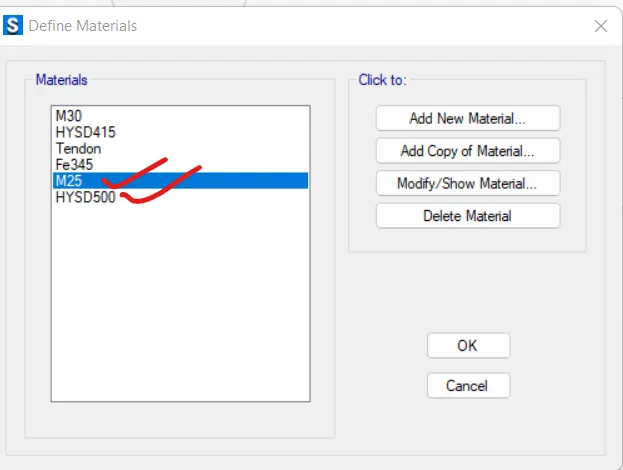
- Defining the material properties-
- Now, Define the slab properties
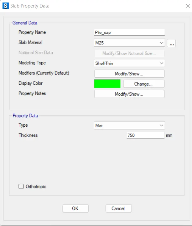
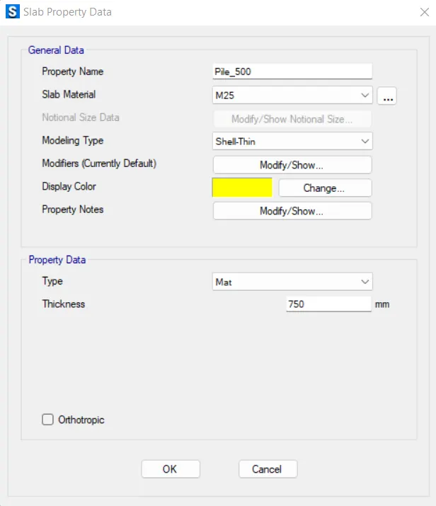
- Here, we are required to define three kinds of slab properties, which are depicted in the snaps below
- We can now start with the geometric modelling,
- First use the tool to draw the rectangular slabs then select the defined slab for mat to draw the pile ca and draw from one end to another in the grid system.
- Go to Draw tab and choose to mark the reference points.
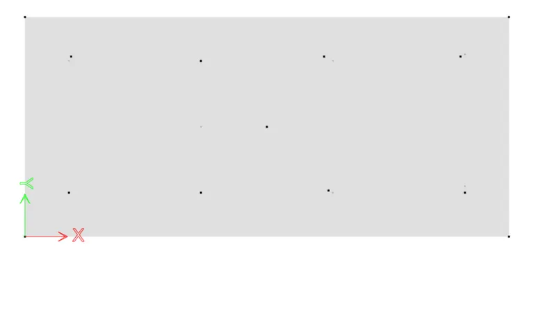
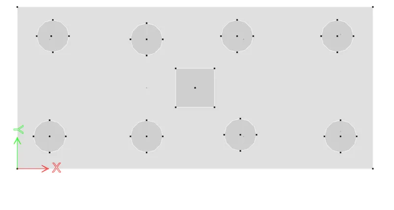
- After marking the reference points use the tool Quick draw area around point and select the property defined for pile and give the diameter of the pile as well and click over the reference points to draw the circular piles.
- The drawn pile system is shown below.
- Now, Define a center point for the column, As we can see the column is also defined at the centre in the pile cap.
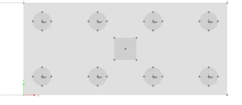
- Assign the spring property into the piles.
- Select the select object cursor from the left and select all the joints of eight piles and go to assign and select Springs.
- Select the defined prperty and apply,ok.
- The assigned spring constants is shown below,
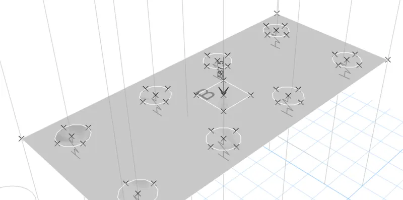
- Now, Assign the loading condition on the column.
- Select the central joint of column then go to assign,joint ,force, give the value of gravity load in negatve direction.
- Apply, ok
- To view the assignment change the view from plan to 3D and can be viewd as follows,
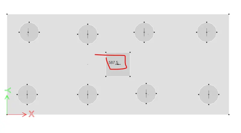
- Now, the model is ready to perform the analysis
Use the play button available above the model space to perform the analysis of the model,
After the analysis the model reflected in the model space as,
Check for settlement-
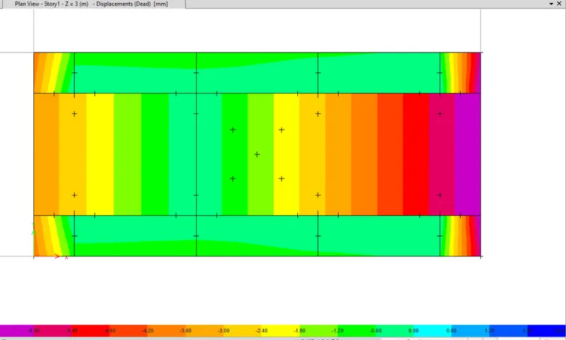
- The maximum displacement(mm),we have arrived here is 6 mm and the maximum allowed from the code of practice is 25 mm.
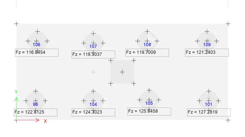
- Reaction Results in response of the 200 Kn pile capacity/Base Reactions at Piles
- Reinforcement Details of the model are as follows,
- Along Strip direction A
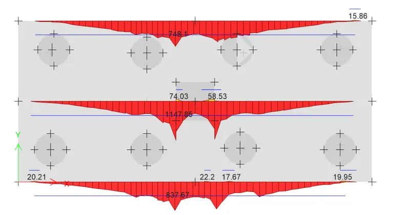
- Along Strip direction B