Project 1 _Creating an Architectural plan for the provided plot size and develop relevant basic structural drawings
1.Dveloping Architectural drawing(Floor plan,Elevation, sections)
Aim:- To draw the floor plan,elevation and section of the plan for the given plot size.
Introduction:-
Floor Plan:-It represents the top view of the planning of the architectural planning in which the arrangement of different components of the house like bedrooms,toile/bathrooms,kitchen,balcony etc are depicted with there dimensions.
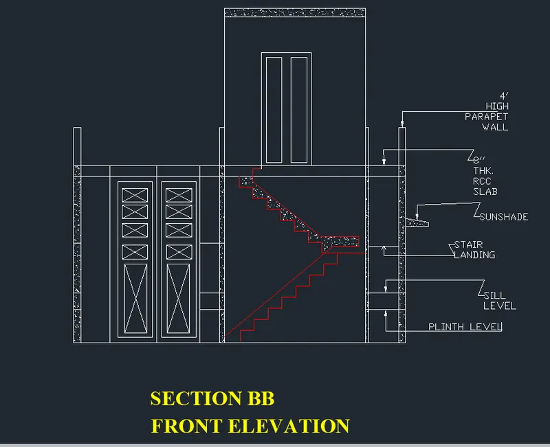
Elevation:- It shows the drawing of the elevation of the building either it may be front ,back or side elevation,represents the height of the building,plinth level,sill level,door window level,sunshade level etc are depicted with there dimensions.
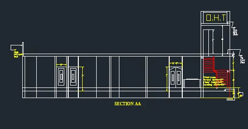
Section:-Section of a building represnts that as if a buillding is cut from anywhere in the plan,how the cut sections components will be visible in an elevated portion and depicted with there dimension as well,like a section of the building is taken in which section cuts a room,stair etc then the elevated portion of the cut components will be represented in the sectional view.
Procedure:-
Step 1:- First a rough sketch of the drawing is prepared on a piece of a paper,after a trial of one or two the most suitable plan which is best fit in the given plot size with proper arrangements of the components of the house like stairs,toilet/bathrooms,bedroom, living room,kitchen/dining,balconies etc are choosen and then start the procedure to draw in the autocad.
Step 2:- Start with the autocad⮕setup with the units
Type-Engineering
Precision-0'0.0''
Insertion unit-inches.
⮕then analyse the screen area required, so, as the plot size is given screen is set using Limmax and the coordinates are (150',150')
⮕zoom⮕all⮕esc.⮕now, the auto cad is ready for drawing.
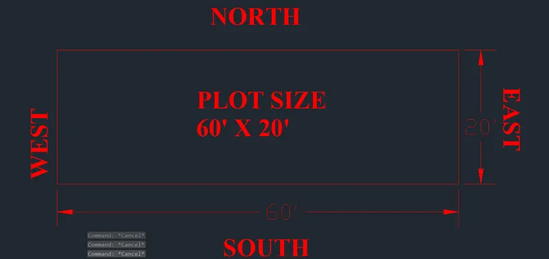
here, first the plot size is drawn and the plot dimensions are marked and the refrence directions are also shown,screenshot of the same is as follows,
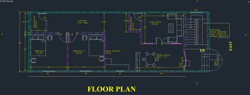
Step 3:-The arrangements with the bedrooms, stairs and other building components in the plot size are arranged and the dimensions are marked while the relevent texts are also assigned.The screenshot of the same is as follows
Step 4:- The section view of AA is shown below in an elevated portion,
Step 4:- The section view of BB is shown below in an elevated portion,
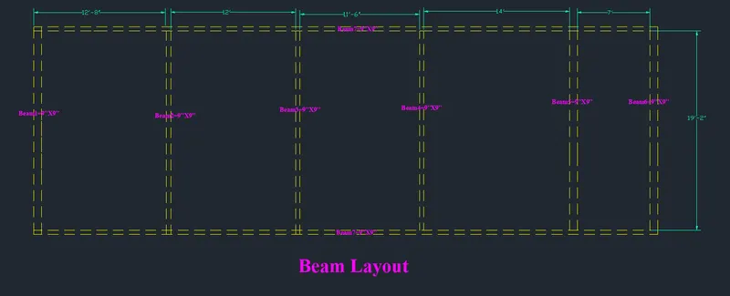
Step 5- Beam layout :- Developing the beam layout is in such a way that all the beams will runs over the 9'' walls,while 5'' walls here, are partition walls so the beam will not come under that ⮕ To do so,converting all the wall lines into hidden/dashed lines to depict the beam layout⮕the end to end distance are also marked for the reference. The drawing is as follows.
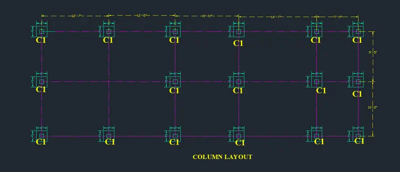
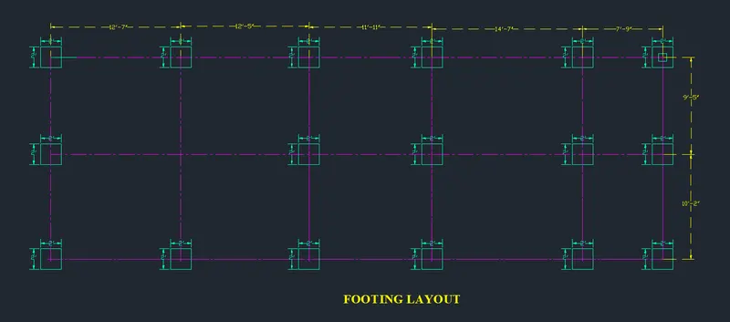
Step 5- Beam layout :- Developing the column layout is in such a way that take the centre lines of all the walls over which the 9'' X 9'' beam is coming⮕the centre point of intersection of x and y lines will be the centre point of the column.⮕create a column of 9'' X9'' and the footing of 2' X2' with the same centre⮕mark the dimensions for footing⮕copy the whole object as one⮕using the geometric centre⮕use the command copy selection and copy them at there respective locations. The centrte to centre distance are marked for the referance. The drawing is as follows.