Analysis & Design of RCC shear walls in the model using ETABS
The etabs file for a G+6 building is provided. Run the analysis and design the RCC shear walls (show in the etabs model). The following challenge deals specifically with the shear wall of size 300x1500 at grid A-11 in the structural model.
- Extract values of longitudinal steel ratio, boundary element length and shear reinforcing ratio from the design results.
- Provide cross sectional steel arrangement of the shear wall from its base up to terrace, in compliance with provisions of IS 13920 – 2016. AutoCAD application can be used for this exercise. Alternatively, it can be drawn by hand as well.
- Provide elevation drawings of the reinforcement details of the shear wall from base up to terrace.
Aim:- To analyze and design the Rcc shear walls of the given model and also perform detailing of the reinforcement for the shear wall of size 300x1500 at grid A-11 in the structural model.
Introduction:-
RCC Shear Wall- Reinforced concrete shear wall is a structural element which is generally provided in the Seismic resistant buildings or structures.
Procedure:-
- Download the given frame model and get open it up with the Etabs software.
- The view of the given model in 3D view,
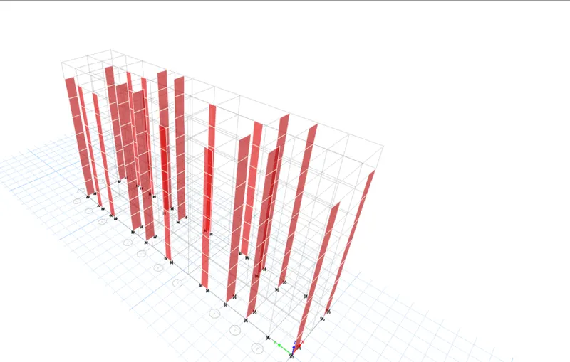
- Make the settings to view the only shear wall for which designing has to be done.
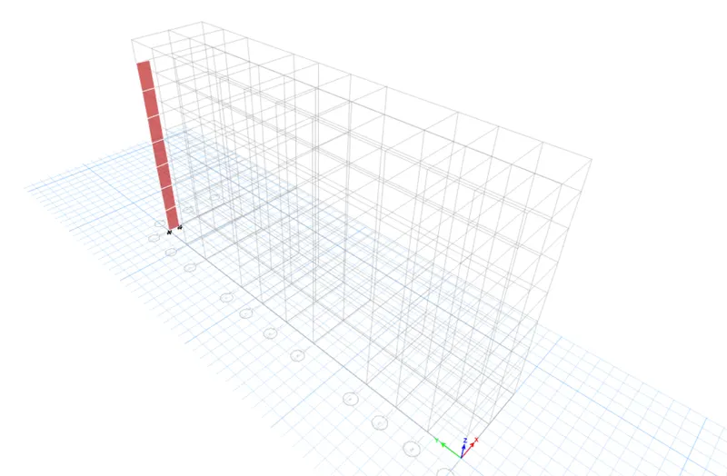
- Select the required wall in plan view⮕set as to show only selected objects which can be viewd as follows,
- Perform analysis for the model,
- Use the play button available in the tool pallettes to perform analysis of the model.
- Once the analysis is comleted the lock available on the tool palletes gets locked and shear wall design option will get activated.
- Now, Perform perform shear wall design for the model⮕click over the icon for shear wall design to perform the design.
- Once the shear wall design is completed, the results for the design can be viewd such as
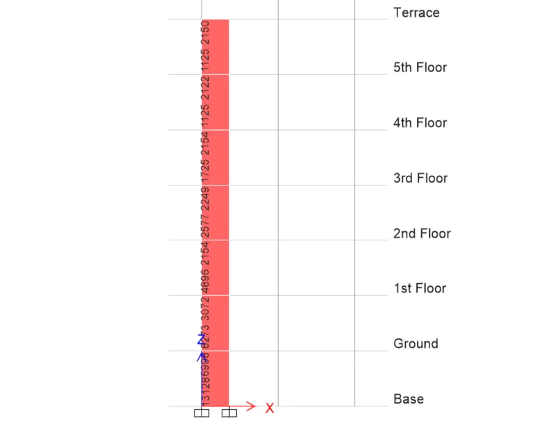
- Pier longitudnal reinforcing areas results(mm^2)-
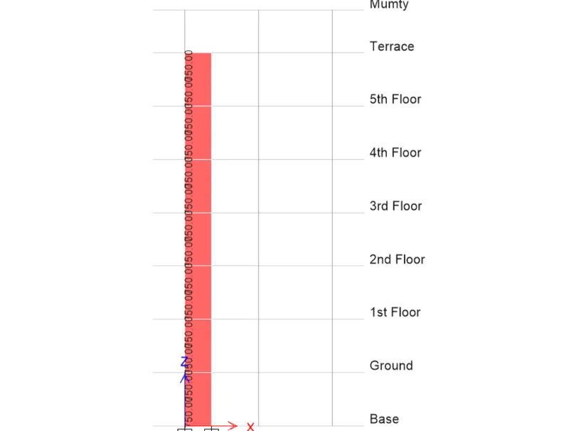
- Pier shear reinforcing(mm^2)-
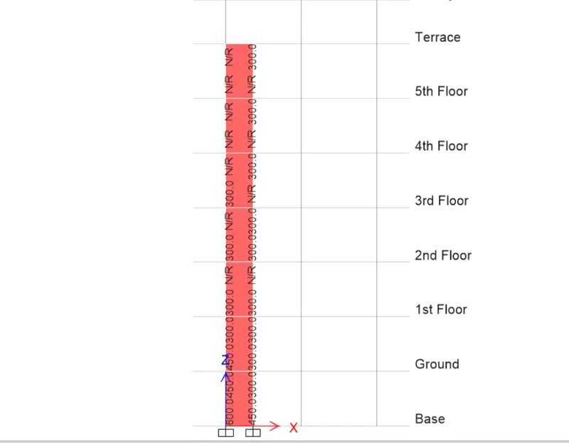
- Pier edge Boundary zone widths(mm),
- As we can see from the Etabs rersult Ast(max) for vertical reinforcement =13128 mm^2
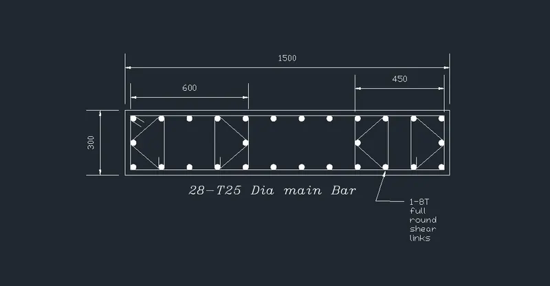
so,Let's provide 28 T-25 which accounts for 13737.5 mm^2 which is greater than the required Ast hence,ok.
- From the Shear reinforcement point of view we can see the reinforcement area is similar all along the height,
Ast=750mm^2
so, let's provide 2L-8T, one 8T accounts for 50mm^2 so,
Spacing= 3000/50=200mm
Hence, Provide 8mm horizontal reinforcement @ 200mm C/C
- Now, From the boundary zone widths we have 600mm on the left while 450 mm on the right side.
- Now, Detailing of the reinforcements in Auto Cad software,
- Plan view of the arrangements, are as follows.
- Elevation view of the arrangements are as follows,
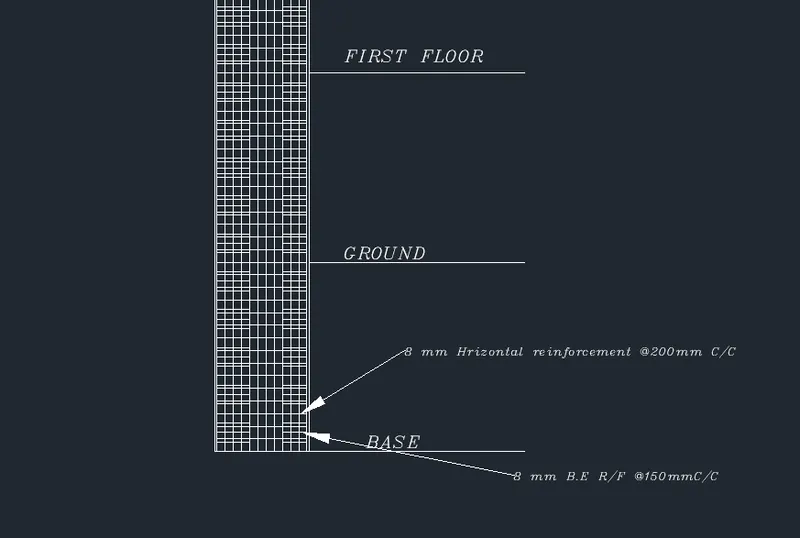
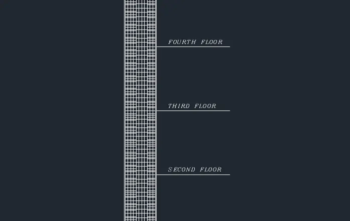
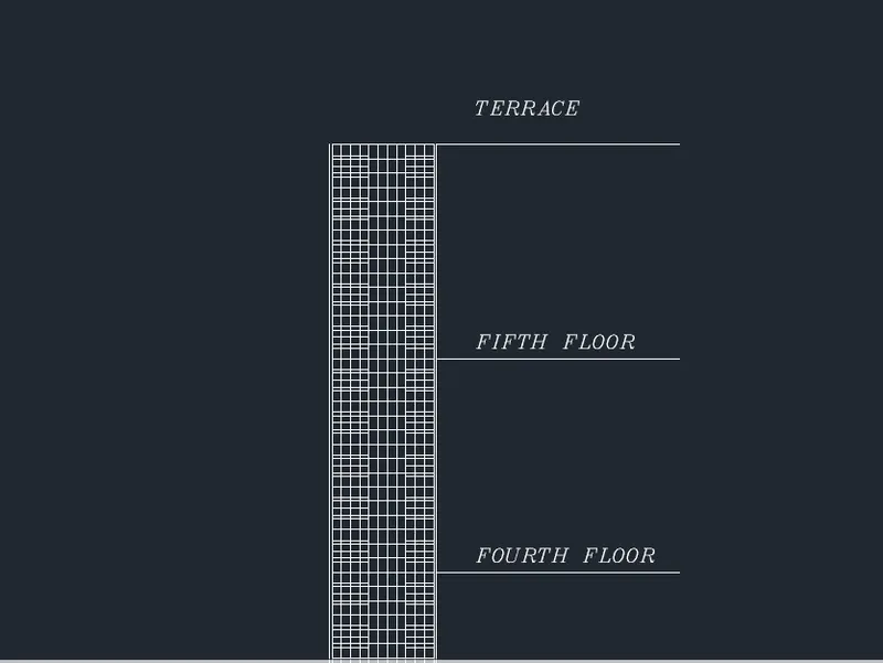
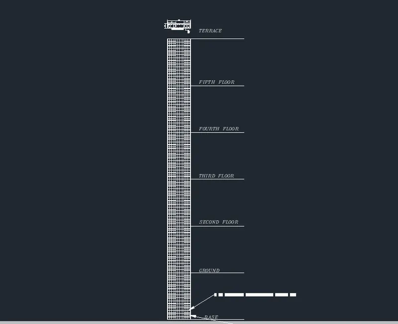
- FULL ELEVATION VIEW FROM BASE-TERRACE,