Mid surfacing and Meshing of a Bottle Cap
Aim:
To check the given component for geometrical errors and mesh with the given element Quality criteria by extracting the mid-surface.
The given element quality criteria is:
|
S.No |
Quality Criteria |
Value |
|
1 |
Target/Average length |
1 |
|
2 |
Minimum Length |
0.5 |
|
3 |
Maximum Length |
3 |
|
4 |
Aspect |
3 |
|
5 |
Warpage |
15 |
|
6 |
Skewness |
45 |
|
7 |
Jacobian |
0.7 |
|
8 |
Minimum Quad Angle |
45 |
|
9 |
Maximum Quad Angle |
135 |
|
10 |
Minimum Tria Angle |
30 |
|
11 |
Maximum Tria Angle |
120 |
|
12 |
Tria Percentage |
15 |
Procedure:
- The geometry is imported to ANSA and topo is performed in order to get a refined geometry. Then we must assign the element size in general, under perimeters title ---> length ---> perimeters and macros as 1 mm in mesh mode for the whole model.
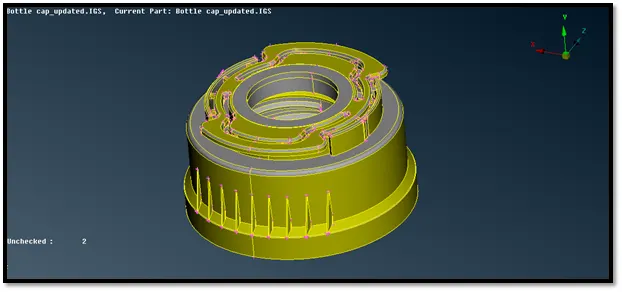
Fig: Imported geometry file
- After which we must do a check geometry for the model by selecting checks---> geometry in the tools bar and fix the errors shown. The various errors are displayed such as needle faces, unchecked faces, triple cons, etc. Auto fix option was opted for resolving these errors.
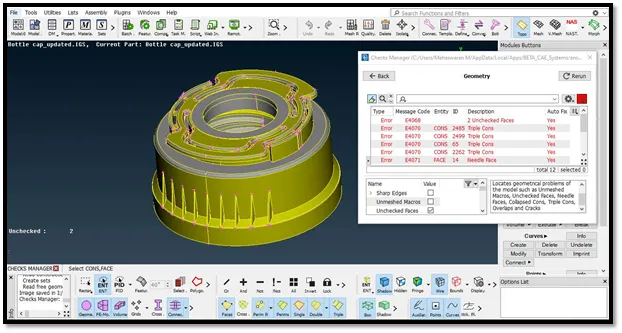
Fig: Applying geometry check
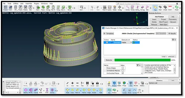
Fig: Using auto fix option
Mid-Surface Extraction:
- The thickness of the geometry was measured before extracting the mid-surface. It was found that the thickness was not uniform across the component and hence shell meshing is to be done.
- In the topo mode, we need to select the faces option ---> offset to extract the mid-surface.
- A red colour line indicates the mid-surface was taken for the component.
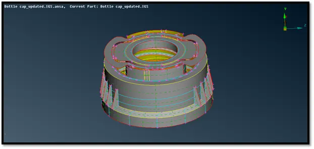
Fig: Extracted mid-surface of the geometry
- We must assign the PID region with thickness after extracting the mid-surface for the component.
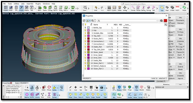
Fig: Assigned properties
- After extracting the mid-surface we must perform a geometry clean-up in the topo mode itself. Features like extend, cut and generate faces were used wherever necessary.
- Meshing:
- Now we will switch to mesh mode and we need to give the shell element size length according to the given input = 5 mm.
- We will now feed the required values specified in the element quality criteria. Average/target length is specified in the mesh parameters as well.
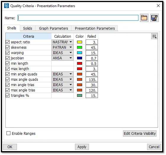
Fig: Values for element quality criteria
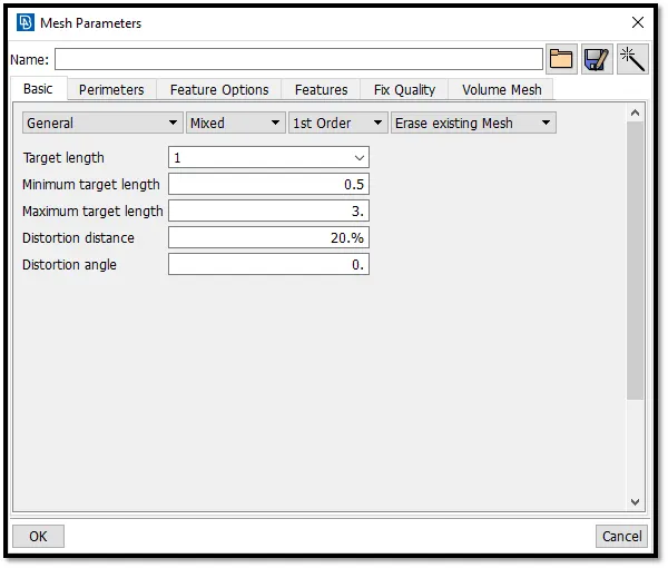
Fig: Mesh parameters
Before Meshing:
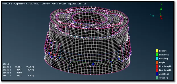
- For meshing batch and best methods were used. Reconstructing was done to obtain a new mesh. Smooth was used to get a proper mesh flow.
- The next keep parameter for better mesh flow is to avoid the opposite trias and trias which are present near the edges or holes or on the fillets. In order avoid these the commonly used commands are split and swap commands under the elements title and also join command under the macros title in the mesh mode.
After Meshing:
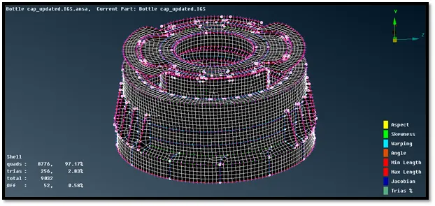
Final FE Model:
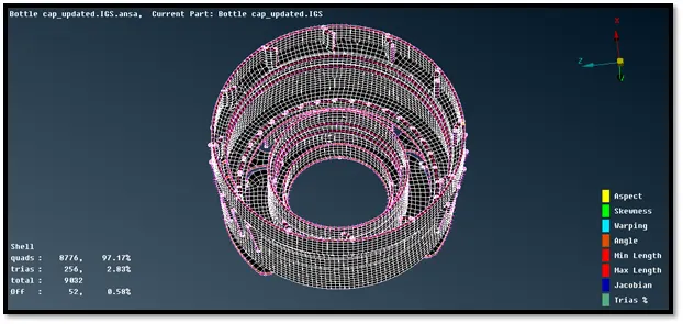
Finally we must check draw shell as solid under presentation parameters in the quality criteria dialogue box.
Conclusion:
The given plastic component was pre-processed successfully and the mid-surface was extracted using various features keeping in mind the varying thickness of the geometry. Meshing was done satisfying all the element quality criteria.
Model access link:
https://drive.google.com/file/d/1gx8NtLWf1N0TVtBvuU6hjZSTSRarm774/view?usp=sharing