Bevel Gear Challenge
Aim:
To write a few words about grid dependency test and to perform the same on bevel gear simulation.
Objective:
1. Write a few words on what a grid dependency test is and its use.
2. Perform a grid dependency test for the Bevel gear simulation for mesh sizes of 6, 5 and 4 mm.
3. Solve for Von-Mises stress, Equivalent elastic strain and Total Deformation using the previously mentioned mesh sizes.
Theory:
Grid dependency test is to investigate how the solution depends on the grid size by running the simulation with refined mesh that is finer the mesh, higher is the accuracy of the result but with additional cost on computation time and computational power. Since, solutions are interpolated at the nodes to get an approximate result, higher the number of nodes and elements higher is the computational time and power required to complete the simulation.
So, the grid dependency test helps in determining optimal mesh size where the accurate result could be obtained keeping in the mind the cost of time and power. Since the result obtained are approximate,
Refining mesh further would result in negligible per cent change is the result but only increase the computational cost in ANSYS-WORKBENCH.
Procedure:
Case Setup:
Geometry Model:
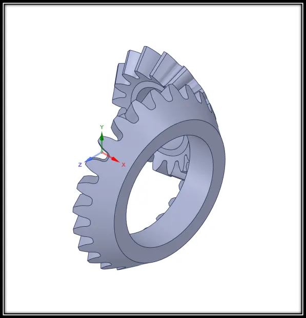
At first, we will import the geometry directly into the geometry modeller using the import option. Then we will enter the Spaceclaim window and we will trim a section on both the gears.
Material:
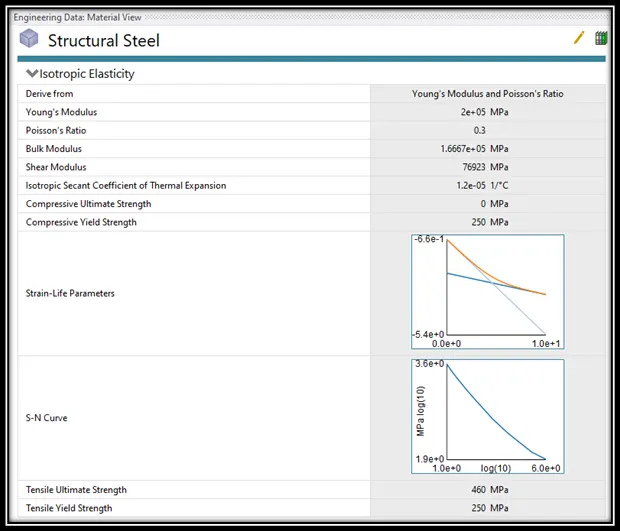
We will be using the default material available in the ANSYS software which is the structured steel.
Pre-processing:
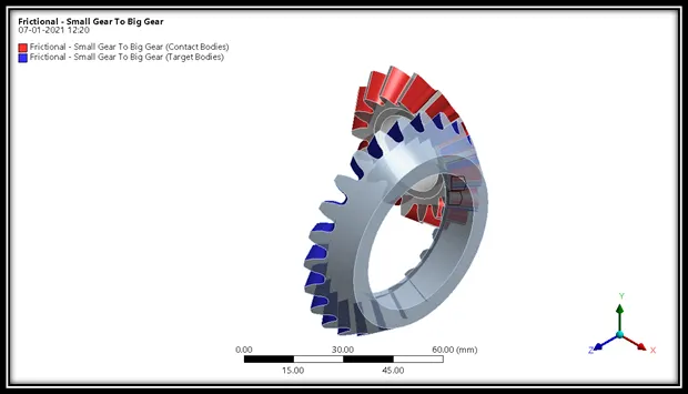
Initially we will be providing the connections for the bevel gear model. The first step is to give contacts for the tooth of the small gear and the big gear in the bevel gear model setup. We will be providing frictional contact by keeping the small gear as the contact body and selecting all the tooths of the small gear. Similarly, we will be keeping the big gear as the target body and selecting all the tooths of the big gear.
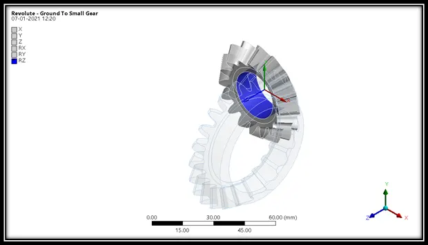
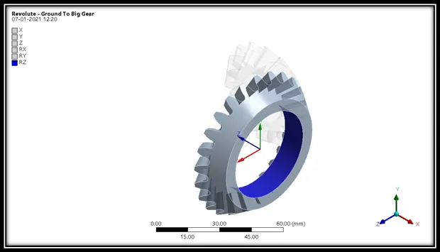
Next, we will provide the joints connections for both the gears. The first connection is the joint revolute connections from ground to the body for the small gear and selecting the reference co-ordinate system correspondingly.
The second connection is also the joint revolute connections from ground to the body for the big gear and selecting the reference co-ordinate system correspondingly.
The analysis settings will be 6 steps.
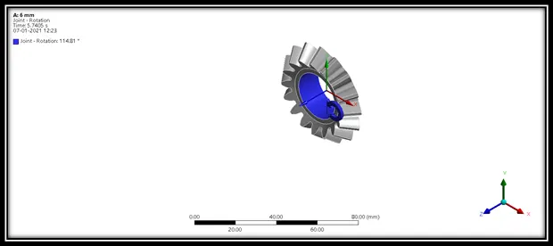
Now, for the load conditions we will be providing joint load at first for the small gear in which we will be providing the type as rotation and with a tabular angle data of 20 degree to 120 degree with increment of 20 per each time step i.e., 20, 40, 60, 80, 100, 120.
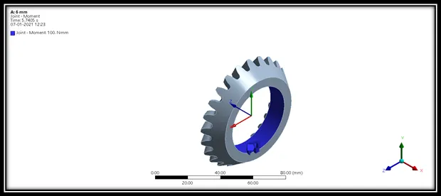
Now, for the load conditions we will be providing the same joint load condition but we will be providing the type as moment and with a tabular data with moment of 100 N-mm for each time step.
Next step is the meshing in which we will performing the grid dependency test for the model for mesh size of 6, 5 and 4 mm.
In order to reduce the setup time for all the three cases of meshing we will be using the parameter set option which will help us in change the parameters which are required to be varied and the output values which are to be compared. And if we select the retain option in it, we will be able to view the setup differently for all the different mesh sizes separately.
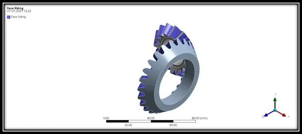
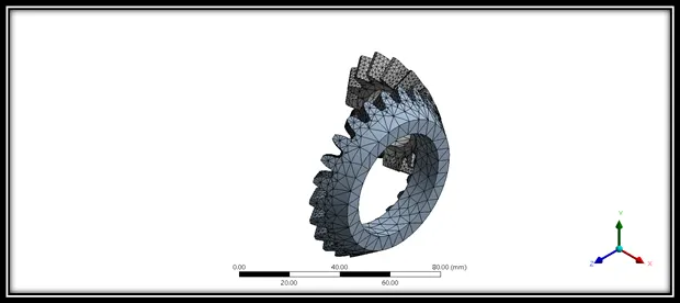
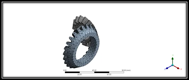
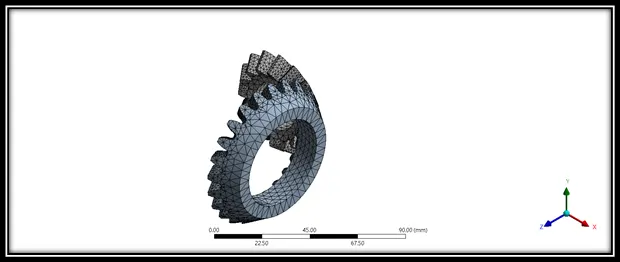
While trying to mesh the case setup we got a bad mesh since the tooth area and gear area was totally different so in order to avoid this, we will be giving mesh sizing only for the tooth area to get a proper mesh on the overall gear setup. The different mesh sizes will not change on the tooth area and it will be a constant element size of 1.75 mm while the element size will vary on the other gear area as 4, 5 and 6 mm.
The mesh sizing of 1.75 mm will be provided for the selected tooth area.
The below images we will give us an overview of the different sizes obtained on the other area of the gear.
6 mm
5 mm
4 mm
Simulation Results:
6 mm mesh:
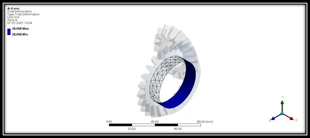
Total Deformation –
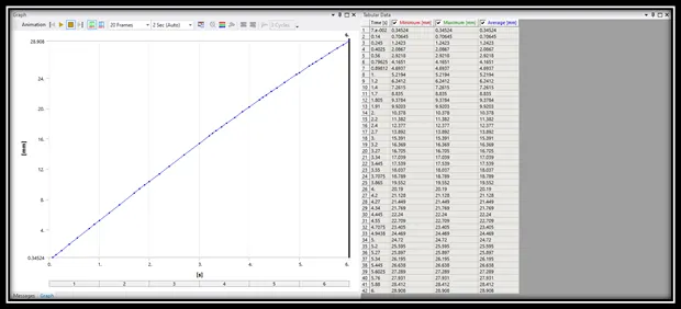
Simulation Video - https://drive.google.com/file/d/1swz_n0uw5svliTaJFBFQkBFaSxTW6UME/view?usp=sharing
Equivalent Elastic Strain –
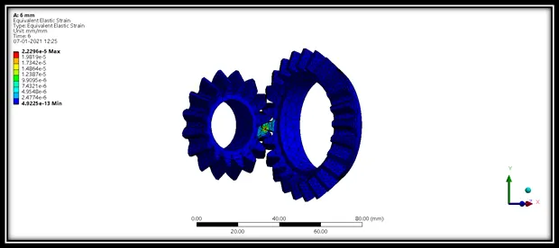
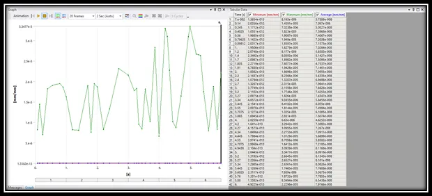
Simulation Video - https://drive.google.com/file/d/1S65cq7v6qYfo0ul7MkWyGlVuF3p5nE9N/view?usp=sharing
Equivalent Stress –
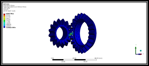
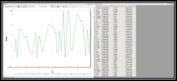
Simulation Video - https://drive.google.com/file/d/1NDjgjKl-fv0y4zw5herjbzINVijNu9MX/view?usp=sharing
5 mm mesh:
Total Deformation –
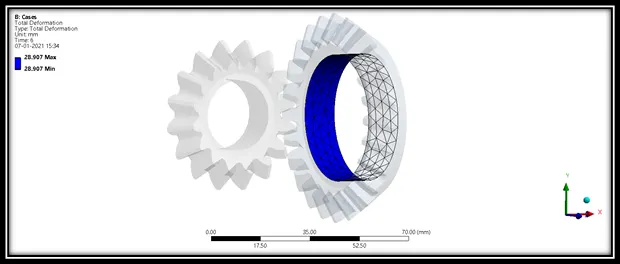
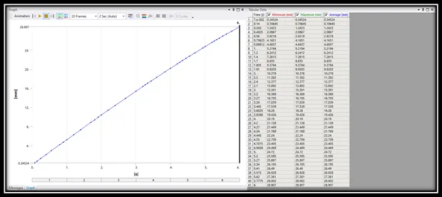
Simulation Video - https://drive.google.com/file/d/1tG-8GokqBY_ellQw3fNHKZ-TvXnSNg5u/view?usp=sharing
Equivalent Elastic Strain –
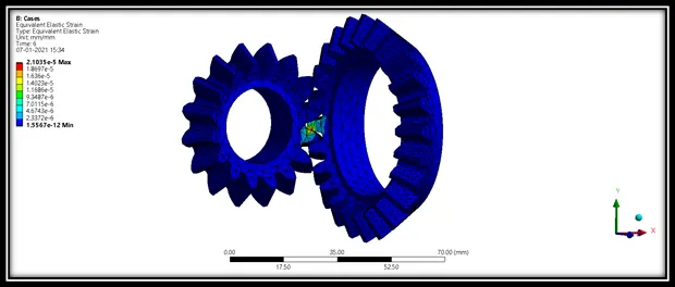
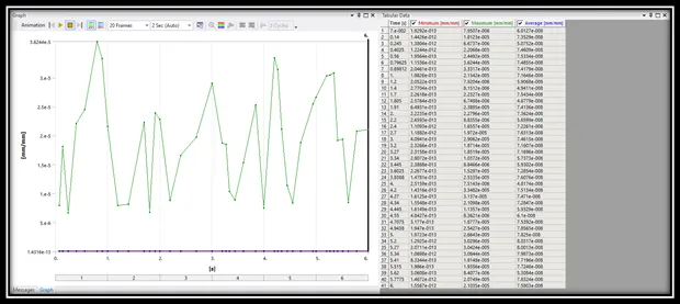
Simulation Video - https://drive.google.com/file/d/1ocmm7QAqThN3kL4bc8VvttarV8xyDZDS/view?usp=sharing
Equivalent Stress –
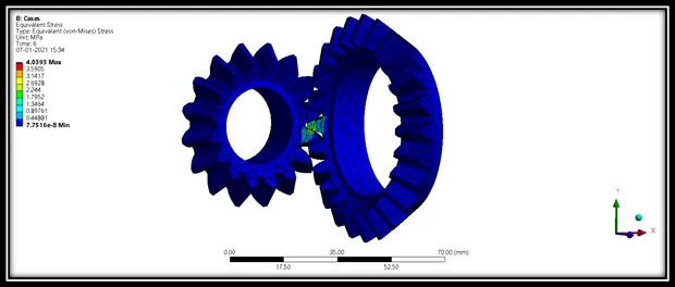
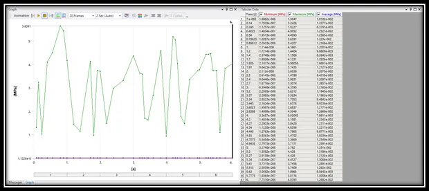
Simulation Video - https://drive.google.com/file/d/1oeTKKRTa-5bl32J1g-WH-jtIGymKEmMq/view?usp=sharing
4 mm mesh:
Total Deformation –
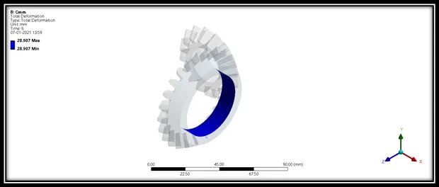
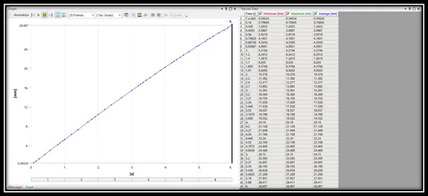
Simulation Video - https://drive.google.com/file/d/1CQuGsvN4yaDXB_QUZ1DjxXPz-mbPgLLl/view?usp=sharing
Equivalent Elastic Strain –
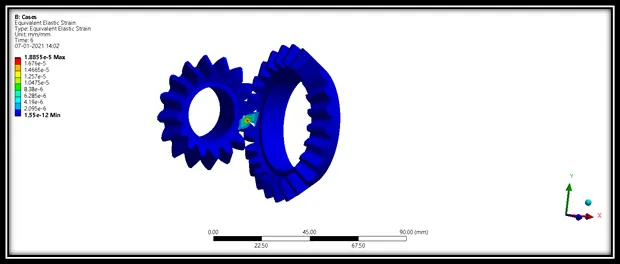
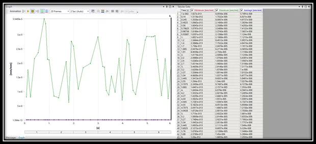
Simulation Video - https://drive.google.com/file/d/1VietI4Irt0f2XPz_Ct3lG8qiph1t1PL6/view?usp=sharing
Equivalent Stress –
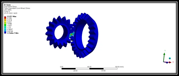
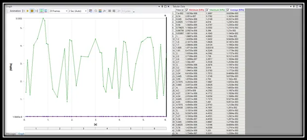
Simulation Video - https://drive.google.com/file/d/12bzrUMuA_E-Na-rdg0TEwUAdqc40Mool/view?usp=sharing
Tabulation:
|
Mesh Sizes |
Max. Equivalent Stress (MPa) |
Max. Equivalent Strain (mm/mm) |
Total Deformation (mm) |
|
6 mm |
5.2591 |
3.3477 e-5 |
28.908 |
|
5 mm |
5.6391 |
3.6244 e-5 |
28.907 |
|
4 mm |
5.5302 |
3.5489 e-5 |
28.907 |
Comparison:
From the tabulation we can see that while simulating with an element size of 6 mm we get a certain result which is not near to the results or values while simulating with an element size of 5 mm and 4 mm. This is known as the grid dependency test and with which we can say that the simulation with an element size of 4 mm has the more accurate and if we try to simulate the model with a more refined mesh size the accuracy of the results wont have much of a difference and it will take a longer computation time.