Thermal Management
Aim:
To summarize about thermal management techniques for electric car battery pack.
Theory:
A battery pack is one of the most important and expensive components that is used in a HEV, EV and PHEV. The batteries used fall in to the category of secondary type meaning that they are rechargeable and are all based on lithium ion chemistries. The chemical reactions that occur in a single cell between the electrodes and the electrolyte results in movement of ions end electrons which ultimately generates a direct current through the external circuit which we use. A single cell is capable of producing a nominal voltage of approximately 3.6V, and so battery packs consist of modules which contain several cells connected together in series and/or parallel arrangements to be able to generate the required energy for the automotive application. For instance, the Tesla model 3 battery pack consists of 2170 lithium ion cells to generate a high voltage of 350V. Due to the high energy requirements of a vehicle, a large amount of power is required from the cells in the battery pack working together. The high power requirement from the circuity of the batteries will generate a large amount of heat energy.
Some of this heat energy is useful in the sense that a higher temperature will result in a quicker chemical reaction occurring in the cells and this will allow for more power to be extracted from the cells. The high temperatures will also increase the mobility of the electrons thus reducing the impedance of the cell and increasing its capacity. This is seen from Arrhenius Law which states that the rate at which a chemical reaction takes place increases exponentially as the temperature increases (but this depends more on the chemical reaction taking place and its reactants and products). On the other hand, this heat energy can have a negative effect if the temperatures exceed a certain point. For instance, high temperatures can lead to unwanted irreversible reverse reactions taking place which consume the electrolyte which can cause the permanent damage / failure of the battery. The high temperatures may have a paradoxical effect in increasing rate of the chemical reactions in the cell and this will generate even more heat inside the cell and in extreme cases can result in a "thermal runaway" event in which a fire or explosion occurs. Conversely, the temperature of a cell should not become too low either because the slow rate of the chemical reactions will impair its performance.
It is inevitable that a battery will age and that its performance will also decrease as it is being used. One of the most important factors affecting the performance of a battery is its operating temperature. However, in order to get the best performance from a vehicle powered by a battery pack, the batteries have to be properly managed to ensure that their degradation and decrease in performance is not accelerated. Cells are designed by manufacturers with certain specifications and operating limits. Operation outside of those limits will damage the cells and will accelerate their degradation. For instance, cells are specified with charging and discharge rates which should not be exceeded. Discharging a cell at a current which is higher than the specified value will decrease the cell's capacity. Corresponding to those charge and discharge rates are the allowable temperatures for them which also should be followed. In order for the cells to operate within these limits, a battery management system (BMS) is used. A part of this will also control the thermal behaviour of the cells and these are called battery thermal management systems (BTMSs). These systems will maximise the efficiency of a battery and also extend its working life so that the systems using it will get the most performance out of them for as long as they are used.
We will study about the concepts of BATTERY-TECHNOLOGY and HEV in general.
BTMS:
Battery thermal management systems are designed with four main essential functions to ensure the restriction of the thermal behaviour of the lithium ion cells within its allowable limits. These four essential functions are:
- Cooling:
Cooling is an obvious essential function because when batteries are operating outside their limits, they become inefficient and generate unwanted heat. This heat has to be removed from the battery pack if the temperature of the cell has dropped below or exceeded a certain level. So, the BTMS needs to be able to cool the battery pack before its temperature can cross its allowable limits.
- Heating:
Opposite to the cooling requirement, there are instances when the temperature of the battery pack may become too low which will also impair its performance. This may occur in environments with cold climates. As a result, the BTMS must have a heating function to increase the battery pack's temperature before it gets too low and keep it within the allowable limits so that its performance isn't affected.
- Insulation:
Insulation is important because if the temperature difference between the environment and the cell is too great, then the cell will get influenced by the environment's temperature. For instance, if the environment is hotter than the cell, the cell temperature will increase. Conversely, if the environment is much colder than the cell, the cell temperature will decrease. In either case, there is a risk of the cell temperature falling outside the allowable limits, and the BTMS needs to have insulation to prevent this.
- Ventilation:
Ventilation is needed for two reasons. The first is that it will allow for cooling of the battery pack when it gets too hot. The second reason is that the hazardous gases produced by the battery pack need to be removed and this is combined with the ventilation and cooling systems.
BTMS Technologies:
Air Cooling and Heating:
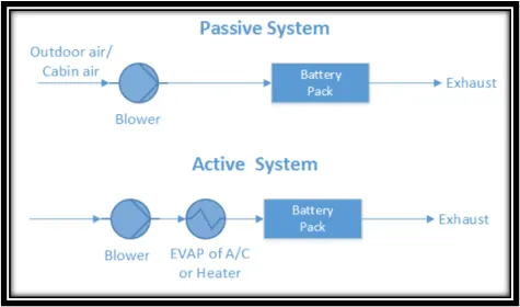
Air cooling and heating systems will use air as the thermal medium. The air used by this system can be taken from the atmosphere which is done in passive air systems. Otherwise the cold air coming from the air conditioning systems in the vehicle can be used as is done in active air systems. Passive systems can provide cooling and heating power in the order of hundreds of Watts whereas active air systems can provide up to 1kW. In both systems, the air is supplied to the battery pack by a blower and so both systems come under the category of "forced air systems". The diagrams below show the working of both systems.
In the passive system, we can see that outdoor air or cabin air is taken in by the blower and supplied directly to the battery pack. The used air becomes hot and is made to exit the air system through an exhaust port. This is the same process used in active systems with the only difference being that the blower will supply the evaporated air of the AC or the heater to the battery pack before leaving through the exhaust.
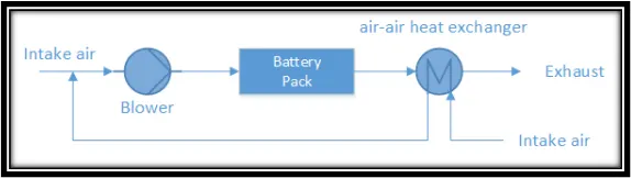
Air systems will provide the main functions of heating, cooling and ventilation with the exception of insulation. The air leaving through the exhaust port cannot be reused by the air system. With the help of a modification, the air system can be fitted with an air - air heat exchanger to recover the heat from the exhaust air and prevent the exhaust air from mixing with the intake air. This is very useful as it can provide the heating function to warm up a battery if it gets too cold. Also, this feature increases the efficiency of the air system in that the heat removed is used again. The diagram of this modified system is shown below:
Forced air systems are beneficial in that they have good reliability and low maintenance, although they have poor thermal management. During high ambient temperatures, the battery pack operating temperature becomes even greater than that of the ambient temperature and this leads to thermal runaway. The temperature gradient between the ambient air and cells is affected by the flow rate of air out of the forced air systems. At higher flow rates, the maximum temperature difference between the cells increases which influences degradation and a decrease in the working life. Air also has a much lower heat transfer coefficient than water and for it to be able to dissipate as much heat as water can, it needs a higher flow rate which will take up more space and more power.
Liquid Cooling and Heating:
In these systems, the thermal medium used is a liquid and there are two main types of liquids used. The first is a dielectric liquid which can come in to direct contact with the cells and an example of such a liquid is mineral oil. The other type of liquid is conducting liquid which does not come in to direct contact with the cells and an example of this type is a mixture of ethylene glycol and water. Depending on the type of liquid used, different constructions are used for the liquid systems. For instance, if the dielectric liquid is used, the battery modules are submerged in them whereas if the conducting liquid is used, they will flow through a jacket around the battery modules or a discrete tubing. The conductive liquid type is preferred over the dielectric type because it will ensure that the battery module is kept separate from the liquid which is safer.
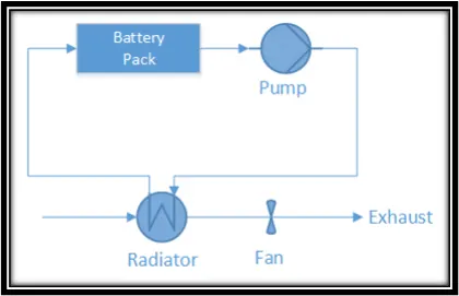
Liquid systems can also be subdivided in to passive and active systems both of which use heat sinks for cooling. In passive systems, the heat sink used is a radiator and it has no ability to heat. The liquid i.e. heat transfer fluid is circulated by a pump and will absorb the heat from the battery pack and will release it through the radiator. The heat transfer liquid circulates around a closed loop. Depending on the temperature between the ambient air and the cell temperature, the cooling power can be great or poor. Some systems may also implement a fan to aid the cooling process but if the ambient air is too hot or the temperature gradient between the ambient air and cell is too small, then the passive system becomes inefficient. The diagram below shows the working of the passive liquid system.
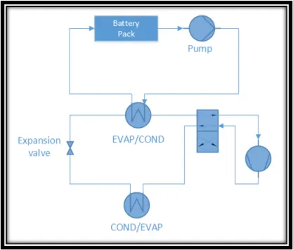
In active liquid systems, there are two loops used. The first loop is the primary loop which is the same as that used in the passive system, where the pump will circulate the heat transfer liquid to remove the heat from the battery pack. The second loop is the secondary loop in which air conditioning occurs. There are two heat exchangers which operate as either evaporators or condensers. When the battery pack needs to be cooled, the upper heat exchanger works as an evaporator where heat absorbed by the heat transfer liquid is cooled. The upper heat exchanger will connect the two loops together. However, when the battery pack needs to be heated, the 4 way valve is switched on, and the upper heat exchanger will work as a condenser, whereas the lower heat exchanger will work as the evaporator. The diagram below shows the working of the active liquid system.
The passive cooling system is the only liquid cooling system which is affected by the ambient temperature because it is the only one that uses a radiator to dissipate the heat. Under normal conditions, this system works fine but if the ambient temperature becomes too high e.g. greater than the battery pack, the system becomes incapable of cooling. Active cooling systems have better thermal performance because they are not as dependent on the ambient temperature because it actively cools the liquid during recirculation. This will keep the cell temperature within the allowable limits and also maintain an even temperature distribution between the cells due to the high heat transfer coefficient of water. However, these systems have more moving parts and so are more complicated and also have a risk of the liquid medium leaking out.
Refrigerant Cooling and Heating:
These systems are quite similar to active liquid systems, in that they will perform both heating and cooling operations with a heat exchanger but instead of using a heat transfer liquid, a refrigerant is used instead to be circulated around the battery pack. These systems are also called direct refrigerant systems (DRS). From the diagram below, we can see that they use a compressor, a 4 way valve and an expansion valve.
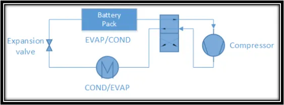
DRS are more efficient than liquid cooled systems because unlike the liquid systems, the DRS uses the refrigerant to directly cool the system instead of using it to cool the coolant which then cools the system. The main disadvantage of DRS is that they also have a complicated structural design, and also have a risk of leaking out from the system. The maintenance of these systems is also difficult since the refrigerant will have to be replaced every once in a while.
PCM:
A PCM is a phase change material and as the name suggests is a material which will transition between phases, namely the solid and liquid phases. When the battery pack gets too hot, the PCM will absorb the heat energy and get melted (phase change from solid to liquid). The heat energy is stored as latent heat until the latent heat reaches its maximum level. Because phase change occurs at constant temperature, the temperature of the battery pack is used for melting the PCM and so is maintained at the melting point of the PCM. This will delay any further temperature increase. When the heat is removed from the PCM to the surroundings, the PCM will return to its solid phase as the latent heat is removed as heat energy. PCMs are used in air cooling and liquid cooling systems as well for a combined effort in battery management. The diagram below shows how the temperature of the cell varies with time and the effect of using a PCM.
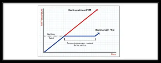
PCM systems perform thermal management quite well even during high ambient temperatures. For instance, even when the ambient temperature is in the range of 45-50 degrees Celsius, the battery pack temperature is still kept below 55 degrees Celsius. This is all due to the PCM having a high thermal conductivity and being able to absorb the latent heat. When the PCM systems are stressed, the maximum temperature difference between the cells is 0.5K and during normal conditions, the same is negligible. One great advantage of PCM systems is that even if one cell undergoes failure, a thermal runaway event will not occur due to the PCM graphite matrix absorbing the heat and spreading it out to the surroundings so quickly. PCM systems have a relatively simple structure, and are lightweight and do not consume much space, however they have the potential to become flammable due to the PCM graphite. PCM systems are preferred for use in colder environments and in space.
Thermo-Electric Module:
A thermo-electric module is one of the ways in which a passive air system's heating and cooling power can be improved upon. As their name suggests, thermo-electric modules can convert a temperature difference to a voltage difference and vice versa. In BMTS, the thermo-electric modules are used to convert a voltage to a temperature difference which is known as the "Peltier Effect". A temperature difference will be created by transferring heat between two electrical junctions. A voltage is applied across the joined conductors and this creates an electric current. Where the conductors join, there will be a change in temperature. Heat is removed at one junction and cooling takes place whereas the removed heat is built up at the other junction. From the diagram below, we can see that two fans are also installed to improve the heat removal by forced convection. The ambient air is at 40 degrees Celsius and when it is passed through the hot side of the thermo-electric module, the cool side will cool the cell/module to room temperature e.g., 25 degrees Celsius. The thermo-electric module can perform both cooling and heating and can be switched between the two very easily, by switching the polarity of the electrodes to create a negative potential difference.
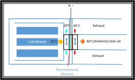
The biggest advantage of thermo-electric modules is that they can reverse the Peltier effect to turn the heating element in to a cooling element simply by reversing the voltages and hence the polarity of the thermo-electric element. Thermo-electric modules are simple in structure and lightweight and since they have no moving parts, they are very reliable, durable and have low maintenance. Even if they undergo failure, they can be replaced very easily and quickly. The main disadvantage of thermo-electric modules is in their efficiency which is quite low. On average, the highest efficiency obtainable by a thermo-electric module is 80% which means that they will have to produce more power than heat generated. Their efficiency is mainly dependent on the temperature gradient between the ambient air and cell and the higher the gradient, the lower the cooling capacity becomes. The other obvious problem, which remains unsolved is that 2 sides of the thermo-electric element where one side is hot and the other is cold are too close to each other.
Heat Pipe:
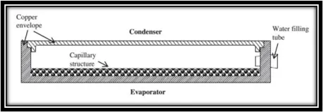
A heat pipe is the second method in which the heating/cooling ability of passive air systems can be improved upon. From the diagram below, we can see that there is a flat copper envelope and it is under a partial vacuum. A capillary structure is present made of sintered copper powder. The heat pipe uses water as the working fluid. There are two heat pipes used, one at the evaporator side and the other at the condenser side. The evaporator side is at lower pressure. Heat from the battery (found below the evaporator) is absorbed by the water to become vapour at lesser than 100 degrees Celsius. The vapour will condense at the condenser and dissipate the heat to the surroundings. The condensed water is then sent back to the evaporator to repeat the process. Compared to the thermo-electric module, the heat pipe is more reliable because there are lesser moving parts and does not require any energy to function. However the disadvantage of heat pipes is that they cannot perform heating.
PTC Heater:
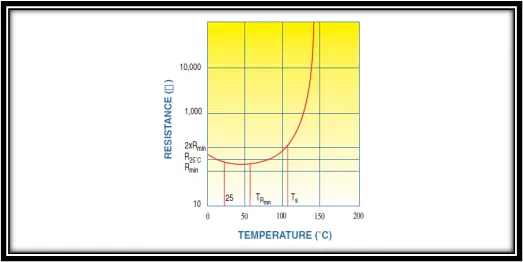
A PTC heater is a thermistor which uses a positive temperature coefficient material. This means that the resistance of the material will increase as its temperature increases. When a voltage is applied to the PTC heater, an electrical current will flow through it and its resistivity will cause it to get heated up. As its temperature increases, the resistivity will increase as well and the heat power produced decreases. This heat will be transferred from the PTC heater to the object it is attached to i.e. the battery pack. When the amount of heat produced is equal to the amount of heat conducted and radiated away from the heater, the PTC heater will remain at a constant temperature at this point. The temperature of the PTC heater can be fixed by adjusting its resistance. The image below shows the resistance - temperature characteristics of a PTC material.
Combined Cooling System:
Combined Liquid System:
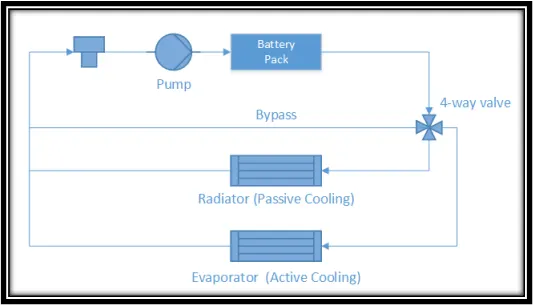
The previously mentioned cooling/heating systems are all adept and work well especially under the right working conditions, however each type of system has its own disadvantages and shortcomings. To avoid this, some of them have been combined to form a single cooling system. The first combined cooling system is the combined liquid system (CLS). This system has four modes of operation:
- Bypass with heater working.
- Bypass without heater working.
- Passive cooling system.
- Active cooling system.
From the diagram below, we can see that the combined liquid system takes the strengths of the passive and active cooling systems and combines them in to one single system. Under normal working conditions, the passive cooling system will perform the cooling operation and have a relatively lower energy consumption. However, when the working conditions become stressful and more extreme, the active cooling system takes over the cooling operation. Although it will consume more energy, it will keep the battery pack temperature well within its limits without risking them due to their superior thermal performance. When the 'bypass with heater working' mode is used, the aim of the BTMS is to heat up the battery pack when its temperature starts falling. When the 'bypass without heater working' mode is used, it is so that the BTMS can cool the battery pack when it gets too hot. The purpose of the bypass is so that there is an alternative route for the pumped liquid to flow through when the battery pack needs to be heated up. This way there is no need to waste energy on cooling hot liquid when the heating is required. The four way valve helps in the diverting of the liquid to the different components depending on the requirement.
CLS & PCM:
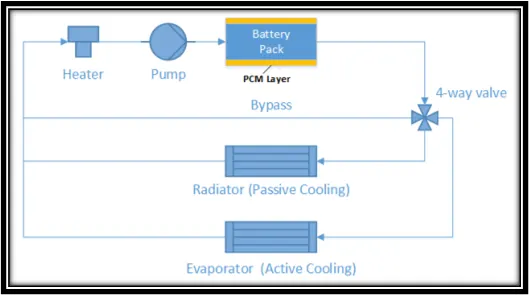
The second combined cooling system is a combination of the previously discussed combined liquid system and the PCM system. In this combined system, PCM layers are fitted on to the battery pack. In spite of PCM systems having good thermal performance, they have a limited working temperature range which is compensated for by the combined liquid system. When the battery pack needs to be cooled, the PCM system will absorb the heat energy and convert it to latent energy when it changes phase from solid to liquid. This will delay further temperature increase of the battery pack. Meanwhile, the CLS will also come in to effect and be circulated around the battery pack by the pump where it can be cooled by either the radiator or the evaporator depending on the temperature gradient between the ambient air and the cell. The same bypass route is available and the four way valve is also present to divert the liquid depending on the requirement. When heating has to be performed, the CLS system will implement the heater to heat up the liquid and pump it around the battery pack. The four way valve will ensure that the heated liquid is sent back to the heater so that it does not get cooled.
Conclusion:
In conclusion, there are various techniques and subsystems being used in battery thermal management systems (BTMS). The implementation of a system is dependent on several factors such as the application, the working environment and the cost which can be afforded. In the application of EVs, HEVs and PHEVs, the thermal behaviour of the battery pack needs to be well controlled by the BTMS so that the individual cells do not get degraded unusually quick when being charged or discharged. The BTMS will ensure that the battery pack's thermal behaviour will follow the tolerable limits specified in the data sheet of the cells it uses. In addition, the thermal management of the battery pack will only work if the battery management system (BMS) can manage the other aspects of the battery pack such as the charging and discharging. This is because the thermal effects on a battery are sometimes a direct result of its own working or can be a side effect of those other aspects. So, all the different management systems need to be working together in sync to ensure the battery pack gives its best performance and working life to the user.