Stateflow of Washing Machine and Simulink Chart for Gear Shift
Aim:
To implement the control logic of a ‘washing machine’ using Stateflow in a given sequence and to make Simulink chart for the ‘gear shift’ logic as per the given conditions.
Objectives:
- Implement control logic of a “washing machine” using Stateflow as per given sequence:
- If the power supply is available, the system gets activated.
- If the Water supply is not available, stop the process & indicate through LED.
- Soaking time should be 200s followed by Washing time of 100s.
- Then rinsing happens for next 20s & dryer runs for 50s.
After all the processes have completed turn on the finished LED.
- Make a Simulink chart for the “Gear shift” logic as per below conditions:
Speed Range (kmph) Gear
0 to 15 1
16 to 25 2
26 to 40 3
41 to 60 4
Above 61 5
Give speed input while the simulation is running & display the gear number.
Theory:
Washing Machine:
A washing machine (laundry machine, clothes washer, or washer) is a home appliance used to wash laundry. The term is mostly applied to machines that use water as opposed to dry cleaning (which uses alternative cleaning fluids and is performed by specialist businesses) or ultrasonic cleaners. The user adds laundry detergent, which is sold in liquid or powder form, to the wash water.
Wash Cycles:
The earliest washing machines simply carried out a washing action when loaded with clothes and soap, filled with hot water, and started. Over time machines became more and more automated, first with very complex electromechanical controllers, then fully electronic controllers; users put clothes into the machine, select a suitable program via a switch, start the machine, and come back to remove clean and slightly damp clothes at the end of the cycle. The controller starts and stops many different processes including pumps and valves to fill and empty the drum with water, heating, and rotating at different speeds, with different combinations of settings for different fabrics.
Washing
Many front loading machines have internal electrical heating elements to heat the wash water, to near boiling if desired. The rate of chemical cleaning action of the detergent and other laundry chemicals increases greatly with temperature, in accordance with the Arrhenius equation. Washing machines with internal heaters can use special detergents formulated to release different chemical ingredients at different temperatures, allowing different type of stains and soils to be cleaned from the clothes as the wash water is heated up by the electrical heater.
However, higher-temperature washing uses more energy, and many fabrics and elastics are damaged at higher temperatures. Temperatures exceeding 40 °C (104 °F) have the undesirable effect of inactivating the enzymes when using biological detergent.
Many machines are cold-fill, connected to cold water only, which they heat to operating temperature. Where water can be heated more cheaply or with less carbon dioxide emission than by electricity, cold-fill operation is inefficient.
Front loaders need to use low-sodding detergents because the tumbling action of the drum folds air into the clothes load that can cause over-sodding and overflows. However, due to efficient use of water and detergent, the sodding issue with front-loaders can be controlled by simply using less detergent, without lessening cleaning action.
Rinsing
Washing machines perform several rinses after the main wash to remove most of the detergent. Modern washing machines use less water due to environmental concerns; however, this has led to the problem of poor rinsing on many washing machines on the market, which can be a problem to people who are sensitive to detergents. The Allergy UK website suggests re-running the rinse cycle, or rerunning the entire wash cycle without detergent.
In response to complaints, many washing machines allow the user to select additional rinse cycles, at the expense of higher water usage and longer cycle time. Bosch for example, in its allergy wash program, incorporates an additional 3-minute rinse cycle with water of at least 60 degree Celsius to rinse off detergent residues and any allergen.
Spinning
Higher spin speeds, along with larger tub diameters, remove more water, leading to faster drying. On the other hand, avoid ironing can be obtained not using spin cycle in the washing machine.
If a heated clothes-dryer is used after the wash and spin, energy use is reduced if more water has been removed from clothes. However, faster spinning can crease clothes more. Also, mechanical wear on bearings increases rapidly with rotational speed, reducing life. Early machines would spin at only 300 rpm and, because of lack of any mechanical suspension, would often shake and vibrate.
In 1976, most front loading washing machines spun at around 700 rpm, or less.
Separate spin-driers, without washing functionality, are available for specialized applications. For example, a small high-speed centrifuge machine may be provided in locker rooms of communal swimming pools to allow wet swimsuits to be substantially dried to a slightly damp condition after daily use.
Dryer
This dry programme is for clean items that need to be aired. It is a quick cycle compared to other programmes on offer. It can be useful for clothing that has been in storage or been in a wardrobe for too long.
Dry is a setting used for cotton, linens and synthetic clothing. This programme will tumble your clothing whilst blowing hot air into the drum to dry the load. Make sure that you are not overloading your drum, otherwise the clothing will not dry effectively. Your washer dryer will tell you what load it can accommodate.
Gear Shifts
A manual transmission (also known as a manual gearbox; abbreviated as MT) is a multi-speed transmission where gear changes require the driver to select the gears by manually operating a gear stick and clutch (which is usually a foot pedal for cars, or a hand lever for motorcycles).
Early automobiles used sliding mesh manual transmissions with up to three forward gear ratios. Since the 1950s, constant mesh manual transmissions have become increasingly commonplace and the number of forward ratios has increased to 5-speed and 6-speed manual transmissions for current vehicles.
The alternative to a manual transmission is the automatic transmissions; common types of automatic transmissions are the hydraulic automatic transmission (AT), automated manual transmission (AMT), dual-clutch transmission (DCT), and the continuously variable transmission (CVT).
In most vehicles with a manual transmission, the driver selects gears by manipulating a lever called a gear stick (also called a gearshift, gear lever or shifter). In most automobiles, the gear stick is often located on the floor between the driver and front passenger, however, some cars have a gear stick that is mounted to the steering column or centre console.
The movement of the gear stick is transferred (via solid linkages or cables) to the selector forks within the transmission.
Motorcycles typically employ sequential manual transmissions, although the shift pattern is modified slightly for safety reasons. Gear selection is usually via the left foot pedal with a layout of 1 - N - 2 - 3 - 4 - 5 - 6.
Model 1:
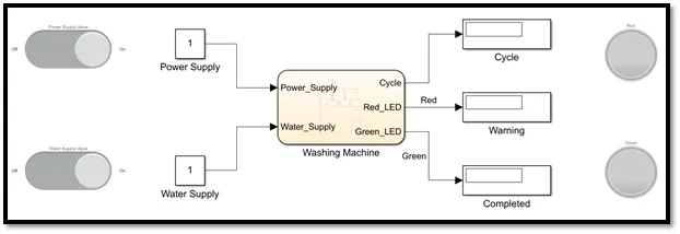
Figure 1: Main model
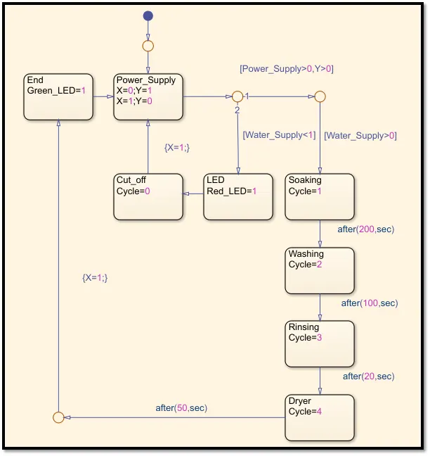
Figure 2: Chart model
Explanation:
- At first, we will create the chart block which is named as Washing Machine in Figure 1 and the chart block is elaborated in the Figure 2.
- In the chart block, we start with the default transition and connect it to a junction which in turn is connected to a junction without any condition so that the process doesn’t terminate before starting.
- This junction is connected to a state block and named as Power Supply state and this is connected to if else condition structure in which the junction is set with a value Power Supply > 0 and Y > 0 where Power Supply is an input value and must be manually fed in the program. Now our washing machine has power supply to it after which it will check for the water supply. Here the value of X will be equal to 0 initially so Y will be equal to 1 and the program will proceed further.
- When the Power Supply value is 1, then our program checks for the condition Water Supply > 0, which is an input value and must be manually fed in the program. If our program satisfies this condition then our program will proceed for the wash cycles if not it will check for the condition Water Supply < 1 because this the port 2 for the if else structure and now if our program satisfies this condition then there is no water supply to our washing machine.
- So, our program will move to the state block named as LED which has the output value Red LED = 1 and if we see in the main Simulink model the display block named as warning will display the value and our lamp block which is connected to this signal coming from the chart as its input value will display red colour as an indication when the signal link reads the value 1 which can be seen in the figure 3.
- We have connected this to the state block named Cut off which will indicate the status of the Cycle = 0, since none of the wash cycles were started and further the state of the condition is X=1 which is again connected to the state block named power supply. Since, X=1 the value of Y=0 and this doesn’t satisfy our first condition which is if else structure so our program will stop which can be seen in the figure 3.
- Now, if the water supply is back our program will proceed further to the wash cycles. Our first wash cycle is soaking and in this soaking state block we will have the output value of Cycle = 1 and if we see in the main Simulink model it will be shown in the display block named status in our main model. This wash cycle must be carried out for 200 seconds so we will give the delay after the soaking state block to be after (200, sec) and then proceed to the next wash cycle.
- The second wash cycle is washing so our program will move to the state block named washing after the run time of 200 seconds which will have the output value of Cycle = 2 and if we see in the main Simulink model it will be shown in the display block named status in our main model. This cycle must be carried out for 100 seconds so we will give the delay in the chart block after the washing state block to be after (100, sec) and then proceed to the next wash cycle.
- The third wash cycle is rinsing so our program will move to the state block named rinsing after the run time of 300 seconds which will have the output value of Cycle = 3 and if we see in the main Simulink model it will be shown in the display block named status in our main model. This wash cycle must be carried out for 20 seconds so will give the delay in the chart block after the soaking state block to be after (20, sec) and then proceed to the next wash cycle.
- The fourth wash cycle is dryer so our program will move to the state block named dryer after the run time of 320 seconds which will have the output value of Cycle = 4 which will be shown in the display block named status in our main model. This wash cycle must be carried out for 50 seconds so will delay in the chart block after the dryer state block to be after (50, sec) and then proceed to the junction.
- Now, after a run time of 370 seconds our four wash cycles for the specified time has been processed after which we must indicate the LED to be in green colour to state that all the wash cycles have been completed successfully.
- So, we connect this junction with a condition X=1 and move to the state block named end which reads the condition Green LED = 1 and if we see in the Simulink model this is given as input signal to another lamp block which will display green to indicate that all the wash cycles have been completed which can be seen in figure 4.
- And further the state of the condition is X=1 which is again connected to the state block named power supply. Since, X=1 the value of Y=0 and this doesn’t satisfy our first condition in the if else structure so our program will stop.
- In the main Simulink model, we have connected two slider switch blocks to make the control of power supply and water supply in the program to be realistic. And this slider switch block when kept in ON condition it inputs the value 1 to the constant block named power supply and when kept in OFF condition it inputs the value 0 to the constant block power supply and similarly this function works for the constant block named water supply.
- Hence, we have successfully implemented the control logic of a ‘washing machine’ using state flow as per the given sequence and also satisfying all the conditions.
Result:
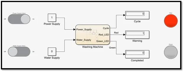
Figure 3: No water supply condition and indicated with LED
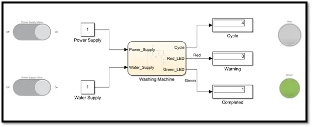
Figure 4: Completed condition and indicated with LED
Model 2:
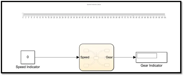
Figure 5: Main model
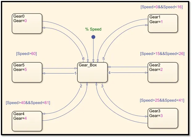
Figure 6: Chart model
Explanation:
- In the figure 6 of the chart block, the input default transition is given as speed using the slider block in the main Simulink model. This slider block is dragged from left to right, in order to decrease or increase the speed and the speed is displayed in the constant block named as speed indicator.
- Now in the chart block we can see that input default transition is connected to the state block named as gear box which is the central state block for our program.
- If the speed input is given through the slider block, then the programs runs to check for the speed condition for the each gear in the chart model and then displays the gear number in the display block of the main model. The speed range conditions for each gear is mentioned in the objectives of this report.
- The figure 7 shows that if the speed is 0 kmph then the gear indicator display block will display the gear to be ‘0’.
- Similarly, in the figure 8 we can that if the speed input is given as 10 kmph then our program will check for the state block condition which satisfies the condition and it is [Speed>0&&Speed<15] which will display the gear to be ‘1’.
- In our objective we can that we must run the simulation and the speed input must be given to the program while the simulation is still running so we must set the run time of the simulation to be infinite i.e. inf.
- And this the reason why we use a slider block to change the speed input while the simulation is running since we cannot input the parameters manually in the speed indicator constant block when the program is running.
- The && condition is used to satisfy the condition only if the input parameters fall into this range of values else it will return to central state block. But in order to make it return to the central state block we connect each and every state block in forward transition and backward transition to the central block.
- Finally, if the speed is above ’61 kmph’ then our gear indicator will display the gear ‘5’ as shown in the figure 9.
- Hence, we have successfully made a ‘Simulink chart’ for the gear shift as per the given conditions.
Result:
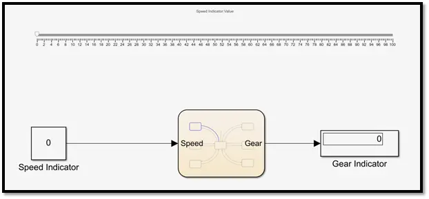
Figure 7: Gear ‘0’ at the speed ‘0 kmph’
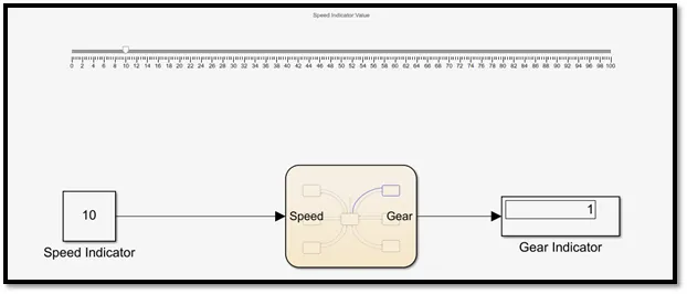
Figure 8: Gear ‘1’ at the speed ’10 kmph’
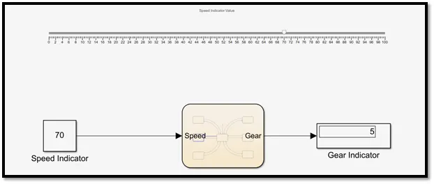
Figure 9: Gear ‘5’ at the speed ’70 kmph’
Conclusion:
- We have successfully implemented the control logic of a ‘washing machine’ using Stateflow as per the given sequence.
- We have successfully made a ‘Simulink chart’ for the ‘gear shift’ logic as per the given conditions.