1D Element Creation Challenge
Aim:
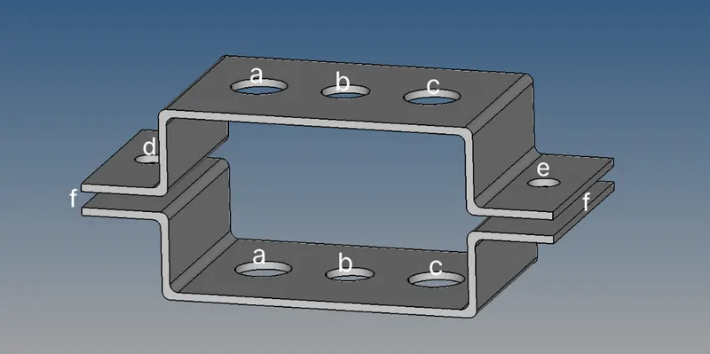
To mesh the given component with the size of 5mm. Create 1D elements on the following component with given cross-section and DOF.
Objective:
a. Rod element: - Translational DOF should be Constrained with RBE2 link
Cross-Section: BOX- Dimension a= 12 mm
Dimension b=10 mm
Thickness t= 0.75 mm
b. Beam element: - All DOF should be constrained with RBE3 link
Cross-Section: I Section- Dimension a= 8 mm
Dimension b= 10 mm
Dimension c= 8.5 mm
Thickness t1= 0.75 mm
Thickness t2= .6 mm
Thickness t3= .6 mm
c. Bar element: - Constrain only xand y DOFs With RBE3 link
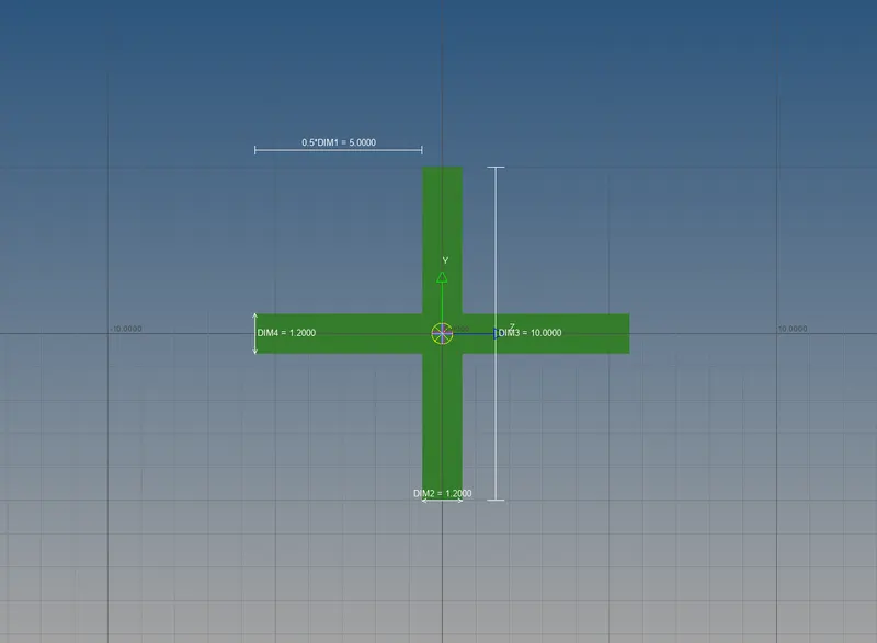
Cross-section: X section- Dimension DIM1= 5 mm
Thickness DIM2= 1.2 mm
Dimension DIM3= 10 mm
Thickness DIM4= 1.2mm
d& e. Apply the massof magnitude 10 with RBE2 link
f. Join the two components with Spring elements
Procedure:
Initially, we will import the geometry model into HyperWorks and then we will be deleting the solids and then create the mid-surface for the surfaces.
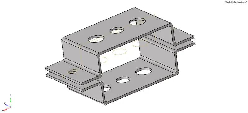
After deleting the solids, the surface alone which are available is as follows.
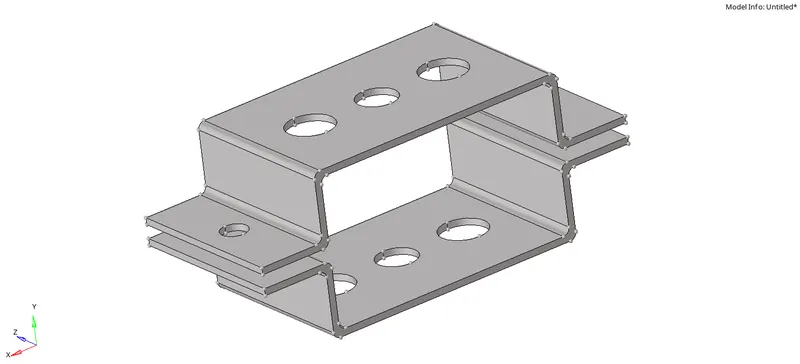
And then create the mid-surface for the two brackets and assign component ID for the mid-surfaces.


Since, there are holes in the component we will create washer elements.


The updated component obtained is as follows in the image below.
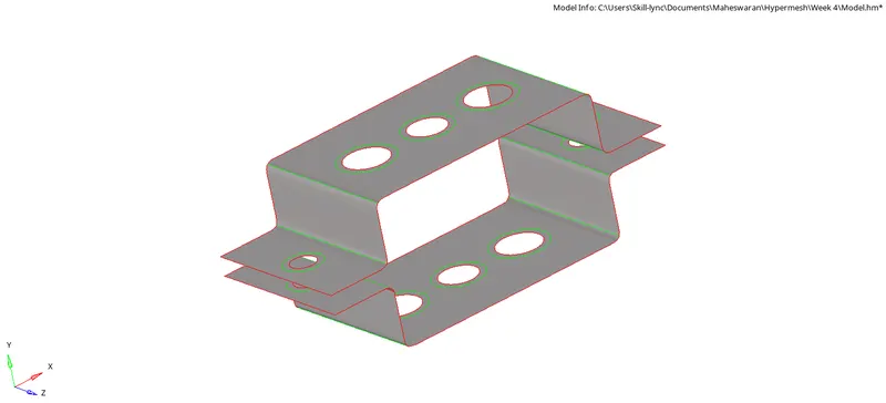
We will now give auto-mesh for the component with an element size of 5 mm and assign proper node numbering for the holes and washers.
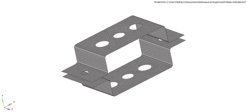
After which we will proceed to provide the objectives which was discussed. The first objective is to provide RBE 2 link in the A region. For the same we will click 1D -----> Rigids as shown in the image below.

And we will constrain the Translational DOF which is dof1, dof2 and dof3.

We will be selecting the required nodes of the hole and the washer as shown in the image below.

The RBE 2 link obtained is shown in the image below.
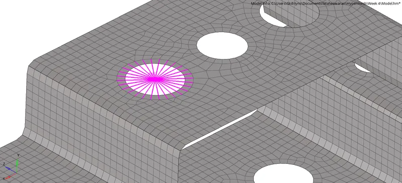
Similarly, the same RBE 2 link must be created for the parallel bracket hole.
The second objective will be to provide RBE 3 link for the B region as discussed and this can be done by selecting 1D -----> rbe3 as shown in the image below.

And in which all the DOF must be constrained.

The nodes to be selected for creating the RBE 3 link are as follows.
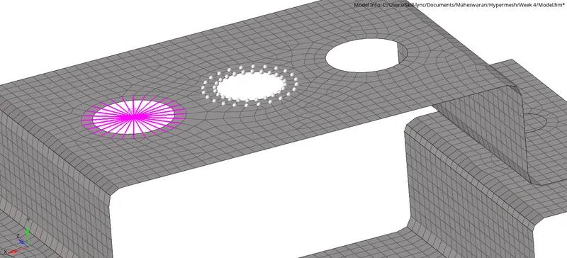
After which we will be creating RBE 3 link for the C region as discussed. In the same rbe3 option we will constrain x and y only i.e., dof1, dof2, dof4, dof5 as shown in the image below.

The nodes to be selected for creating the RBE 3 link are as follows.
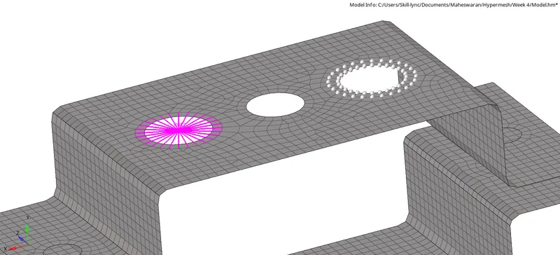
The same is to be done for the parallel brackets. The model obtained after creating the links are as follows.

After which we will be creating RBE 2 link on D and E regions as discussed. In which a mass of magnitude 10 will be applied.
We will be selecting the required option and constraining all the DOF.

The nodes which are to be selected are shown in the image below.
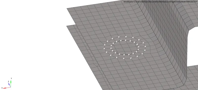
After which for applying the mass of magnitude 10 for the same we will select the option 1D -----> masses as shown in the image below.

For creating the mass, we will be selecting the elem types to be CONM2 and mass = 10

The node to be selected will be at the centre of RBE 2 link which is shown in the image below.
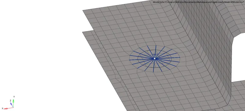
And the CONM2 mass will be created on the RBE 2 link.
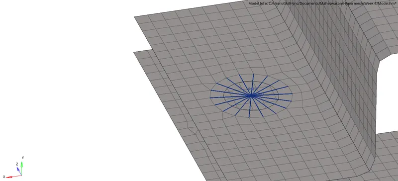
Now, for the spring elements we will be selecting the option 1D -----> springs as shown in the image below.

And then we will be creating springs with elem types to be HMSPRING as shown in the image below.

We will be selecting two nodes i.e., one node from one bracket and another node from another bracket.
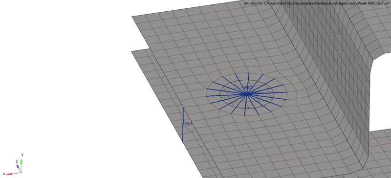
Now, for the A, B and C regions we will be creating the required elements such as Rod, Beam and Bar elements respectively.
For the Rod element we will be selecting the option 1D -----> rods as shown in the image below.

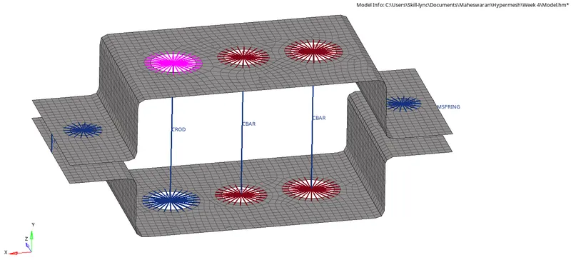
Then we will be selecting the node of the Bracket 1 RBE 2 link and Bracket 2 RBE 2 link in the B region with the elem types to be CROD as shown in the image below.

For the Beam and Bar element we will be selecting the option 1D -----> bars as shown in the image below.

Then we will be selecting the node of the Bracket 1 RBE 2 link and Bracket 2 in the C region with the elem types to be CBAR as shown in the image below.

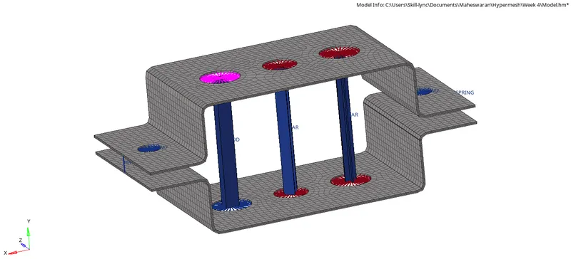
The final model containing all the links and elements is shown in the image below.
Now, we will enter into HyperBeam view mode and create the required elements as follows.
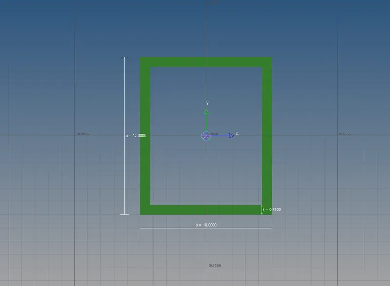
At first, we will be creating the Rod element with a cross-section as BOX with Dimension a= 12 mm, Dimension b=10 mm, Thickness t= 0.75 mm which is shown in the image below.
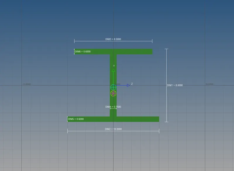
Next, we will be creating the Beam element with a cross-section as I section with Dimension a= 8 mm, Dimension b= 10 mm, Dimension c= 8.5 mm, Thickness t1= 0.75 mm, Thickness t2= .6 mm, Thickness t3= .6 mm which is shown in the image below.
Finally, we will be creating the Bar element with a cross-section X section, which is to be selected as cross section in the HyperBeam view Dimension DIM1= 5 mm, Thickness DIM2= 1.2 mm, Dimension DIM3= 10 mm, Thickness DIM4= 1.2mm which is shown in the image below.
We will be creating separate property ID for the mid-surfaces and the elements.
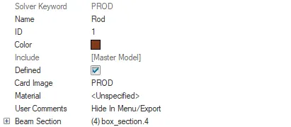
For the Rod element we will be creating property ID as rod with card image PROD and Beam section to be box section.
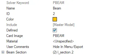
For the Beam element we will be creating property ID as beam with card image PBEAM and Beam section to be I section.
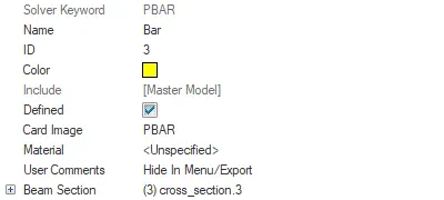
For the Bar element we will be creating property ID as beam with card image PBAR and Beam section to be cross section.
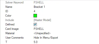
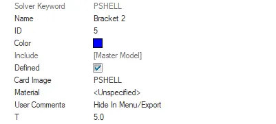
For the Bracket 1 mid-surface and Bracket 2 mid-surface we will be providing card image to be PSHELL with 5 mm thickness.
Finally, we must assign the elements to the 1D elements and the realize the same.
CAD Image: