EV Drive-train
Aim:
To study about the types of power converter circuits and to find out the EV steady state speed for an electric vehicle’s powertrain.
Objective:
- Which types of power converter circuits are employed in electric and hybrid electric vehicle?
- An Electric Vehicle's powertrain with 72V battery pack in shown in the diagram below. The duty ratio for acceleration operation is 'd1' and for the braking operation the duty ratio is 'd2'.
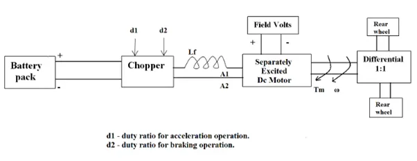
The other parameters of the electric vehicle are given below,
Motor and Controller Parameters:
Rated Armature voltage= 72 V
Rated armature current= 400 A
Ra= 0.5Ω, KΦ= 0.7 Volt second
Chopper Switching frequency= 400 Hz
The vehicle speed-torque characteristics are given by the below equation
`T = 24.7 + (0.0051) omega^2`
What is EV steady state speed if duty cycle is 70%?
- Refer to the blog on below topic:
Induction Versus DC brushless motors by Wally Rippel, Tesla
Explain in brief about author’s perspective.
Model 1:
The different types of power converter circuits used in electric and hybrid electric vehicles are as follows:
- AC to DC = Rectifier: It converts AC to unipolar (DC) current
- DC to AC = Inverter: It converts DC to AC of desired frequency and voltage
- DC to DC = Chopper: It converts constant to variable DC or variable DC to constant DC
AC to DC Converters or Rectifiers
An AC to DC converter is also called a rectifier, which converts AC supply from main lines to DC supply for the load. Here, the transformer adjusts the primary AC source supply to the input of rectifier stage. Usually it is a step-down transformer that reduces the supply voltage to a circuit operating range.
The rectifier converts the low voltage AC supply into DC supply.
It comprises diode and/or thyristors based on type of rectifier. The output of the rectifier is of pulsed DC and hence it is filtered using filter circuit, which is usually made with a capacitor or a choke.
The control block controls the firing angle of thyristors in case of phase-controlled rectifiers. Since the diode is not a controllable device, control block is not needed in case of diode rectifiers.
DC to AC Converters or Inverters
These converters are connected between DC source of fixed input, and variable AC load. Most commonly, these DC to AC converters are called as inverters. An inverter is a static device that converts fixed DC supply voltage to variable AC voltage.
Here the fixed DC voltage is obtained from batteries or by DC link in most power electronic converter. The output of the inverter can be variable/ fixed AC voltage with variable/fixed frequency.
This conversion from DC to AC along with variable supply is produced by varying the triggering angle to the thyristors. Most of the thyristors used in inverters are employed with forced commutation technique.
These can be single phase or three phase inverters depending on the supply voltage. These converters are mainly divided into two groups. One is PWM based inverters and other multilevel inverters.
Further, these are classified voltage source inverter and current source inverter. Each type is subdivided into different types such as PWM, SVPWM, etc. Multilevel inverters are more popular in industrial applications.
The inverters overcome the drawbacks of PWM based inverters.
DC to DC Converters
Many DC operated applications need different levels of DC voltage from a fixed DC source.
Some of these applications include subway cars, DC traction systems, control of large DC motors, battery operated vehicles, trolley buses, etc. They require variable DC to produce variable speed, so a power conversion device is needed.
A DC chopper is a static device that converts a fixed input DC voltage to variable DC output or a fixed DC output of different magnitude (which can be lower or higher) than input value.
The chopper circuit is connected between DC input source and DC load. This chopper consists of power electronic switching devices such as thyristors which are connected in such a way that they produce required DC voltage to the load.
The output voltage is controlled by adjusting ON time of the thyristor (or switch) which turn changes the width of DC voltage pulse at the output. This method of switching is called as pulse width modulation (PWM) control.
The output of the chopper can be less or greater than the input and also it can be fixed or variable. These can be unidirectional or bidirectional devices based on the application it is intended for.
DC choppers are mainly used in DC drives, i.e., electric vehicles and hybrid electric vehicles.
AC to AC converters:
They are not used in EV’s and they give variable frequencies output and voltage at variable outputs. They are used in fan regulators.
Model 2:
Rated armature voltage,
`V_a = 72 V`
Voltage after 70% duty ratio = 72*0.7 = 50.4
The vehicle charactersitics are given by the equation,
`T = 24.7 + (0.0051) omega^2` -----> (1)
The derived formula for motor speed characteristics is,
`T = V/R . K - K^2/R . omega`
After substituting the input values we have,
`T = (50.4*0.7)/0.5 - 0.7^2/0.5 . omega`
`T = 70.56-0.98 omega`-----> (2)
Now comparing equation (1) and (2), we have
`24.71 + (0.0051)omega^2 = 70.56-0.98 omega`
`0.0051 omega^2 + 0.98 omega - 45.85 = 0`
We will use the quadratic equation formula to solve the equation,
`omega = (-0.98 + sqrt ((0.98)^2 - 4(0.0051)(-45.85)))/(2*0.0051)`
`omega = 38.92` rad/s
Model 3:
According to the blog “Induction versus DC Brushless motors by Wally Rippel, Tesla”, the author wants to highlight topics related to EV technology, especially related to DC brushes and motors.
According to him, DC (direct current) is replaced by DC Brushless motors or Induction motors. Also, lead-acid battery is replaced by lithium ion batteries for EVs. He said that there will be the future of both the components induction and brushless DC motors depends upon their demands and uses.
DC Brushless motor:
The technology behind the DC Brushless motor is that it has more than 2 permanent magnet which generates a DC magnetic field. For better torque generation in rotor and stator, a current flow in winding and this happen due to magnetic field near the stator. According to him, the brushless motor needs a proper flow of current into rotor and stator if it will be not in a proper way then the current will not generate and there will be a decrease in torque. To maintain the electrical to mechanical conversion there should be a smooth flow of current otherwise this brushless motor is not useful. A brushless motor does not create any starting torque.
The advantage of a DC brushless motor is that there is low heat generation in the rotor, its cooling capacity is better as compared to induction motor drive, also peak power efficiency is high. Another difference is that the DC brushless drive, also peak power efficiency is high. Another difference is that the DC Brushless drive can also operate at unity power factor, whereas the best power factor for the induction drive is about 85 per cent. This means that the peak point energy efficiency for a DC Brushless drive will typically be a few percentage points higher than for an induction drive.
Induction motor:
The technology behind the induction motor is that it basically uses a 3-phase induction motor which was discovered by Nikola Tesla in 1889. In induction motor there is the use of steel laminated devise instead of magnets. Currents flowing in the stator windings produce a rotating magnetic field that enters the rotor. In an induction, motor current interacts with the magnetic field to produce a force which is required for rotor torque. The induction motor is compatible with any power sources. An induction motor cannot operate from DC voltage it always require AC voltage.
The induction motor does not have any magnets and in this the B field is adjustable. In an induction, motor B field is proportionate to V/f (voltage to frequency). This technology is used to reduce the magnetic losses and the overall efficiency will be increased. An induction motor has many advantages that it does not have any magnetic losses and conduction losses, due to which efficiency will maintain at maximum peak. This all lead to increasing the performance, induction motor is very useful and efficient for high performance. In an induction motor, the peak efficiency is less but it works smoothly better. The controlling of induction motor or mechanism is more complex. Also the torque generation is low and the motor temperature increases when it works at high speed.
Inference:
Now, the question is that which one is the best brushless DC motor or induction motor, then during 1990s General Motors EV-1 and Tesla Roadster work by using induction motors and rest all HEVs were using DC Brushless motors. Both the drives mean DC Brushless and induction motors using 3-phase modulating inverters. The only difference is in rotor and inverter controller of the motors.
According to sensors, the DC Brushless motor requires absolute position sensors whereas induction motor only needs speed sensors.
Another factor is related to the cost of magnets that permanent magnet is costly in kg. Also, the permanent magnet rotor needs more careful maintenance and it’s difficult to handle. So, the cost of induction motor is less.
The conclusion according to the author is that the induction motor drives is only best for pure high –performance electric vehicles whereas DC Brushless drives are beneficial for all hybrids as well as plug-in hybrid vehicles.
Conclusion:
- We have discussed about the different types of power converter circuits employed in electric and hybrid electric vehicles.
- The EV steady state speed of an EV drivetrain was found out with the given input values.
- We have studied a blog on the topic Induction Versus DC brushless motors by Wally Rippel, Tesla and explained about the author’s perspective.