Ip-Substrate Project
Aim:
In this Project-1, ANSA pre-processor is used to generate mid surface using various options like casting, offset, middle, etc. Created 2D interpretation of the parent geometry. Extended mid surfaces in order to connect all the generated mid surfaces. Mesh the component using spot with given quality criteria. Cleared off elements without any kinks or raised edges. The given quality criteria is as follows:
|
S.No |
Quality Criteria |
Value |
|
1 |
Target/Average length |
4 |
|
2 |
Minimum Length |
2 |
|
3 |
Maximum Length |
6 |
|
4 |
Aspect |
3 |
|
5 |
Warpage |
15 |
|
6 |
Skewness |
45 |
|
7 |
Jacobian |
0.7 |
|
8 |
Minimum Quad Angle |
45 |
|
9 |
Maximum Quad Angle |
135 |
|
10 |
Minimum Tria Angle |
30 |
|
11 |
Maximum Tria Angle |
120 |
|
12 |
Tria Percentage |
15 |
Objective:
- Importing Instrument Panel geometry into ANSA.
- Clean up the geometry until no topological error is found.
- Generate mid surface for the whole component including features.
- Mesh the component using manual mesh with given quality criteria.
- Improve the mesh flow and solve off elements.
Theory:
A dashboard (instrument panel (IP) is a control panel usually locked directly ahead of a vehicle’s operation. These days’ car dashboards may include so many indicators like speedometer, tachometer, odometer, fuel gauge, turn indicators, gearshift position indicator, seat belt warning light, and engine-malfunction lights. Other features may include a gauge for alternator voltage, indicators for low fuel, low oil pressure, low tire pressure and faults in the airbag (SRS) systems, lighting controls, safety systems, entertainment equipment, navigation systems, etc.
Dashboard can be made from metal as simplest and cheapest way. This could be the same base metal as the car, which is steel or aluminium. The more expensive luxury cars are made of exotic wood with a highly polished finish. Usually, top layer on old cars is PVC. More recently, dashboard coverings have been made of PVC blended with something called ABS. ABS is an acronym for a block copolymer made of acrylonitrile, butadiene and styrene.
Procedure:
Step 1: Importing the Geometry Model
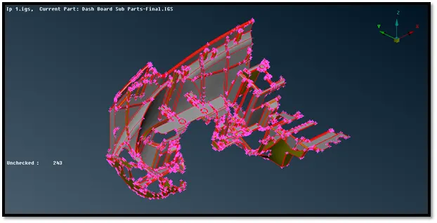
- We first import the CAD model to the ANSA database using the Open option in the File tab and the imported component is shown below:
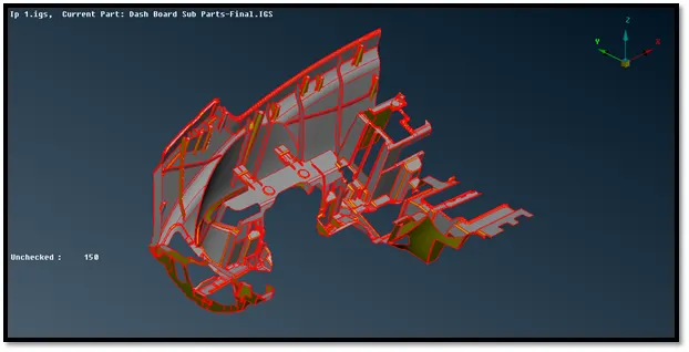
- After that, we set the perimeters and macros of the CAD model to 1 mm for better visualization of all the areas using the Length option present under Perimeters tab of the Mesh module as shown in the images given below:
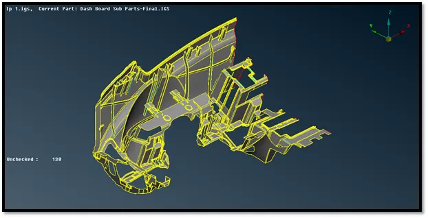
- After that, we perform topology over the whole CAD model so that the surface get properly stitched to each other using the TOPO option present under the Faces tab of the TOPO module as shown in the image given below:
Step 2: Geometry Clean-up
- In this process, we clean up all the errors present in the CAD geometry like unchecked faces, needle faces, triple cons, single cons, cracked faces, etc.
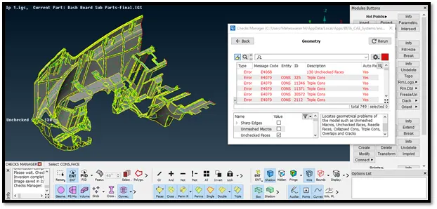
- We go to the check geometry option present in tools tab to check for geometrical errors in the CAD model as shown in the image given below:
- We then, get the clear all errors one by one manually to get a goof geometry of the CAD model and again run the geometry check, therefore we get a check CAD geometry with no errors on it as shown in the images below:
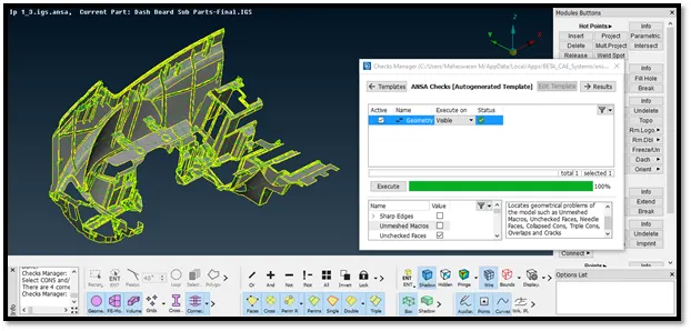
- We store a locked view of the parent geometry before taking the mid surface using the Lock option present in the Focus
Step 3: Mid-Surface Generation
- We have to measure the whole geometry region by region so that we can create a mid-surface without any confusion.
- We use the Measure option present under the Utilities tab to the measure the whole component region by region as shown in the image given below:
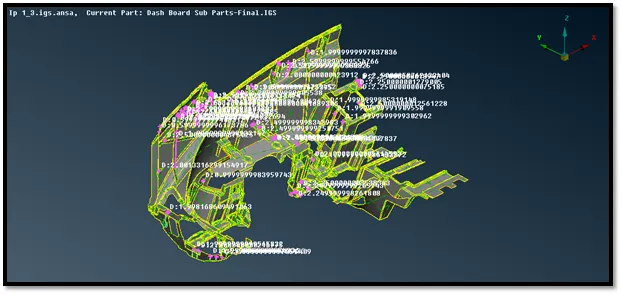
- After that, according to the measurements taken from the parent geometry we start taking the mid-surface for component region by region.
- We use different options to take the mid-surface in different regions like the Offset, Middle, Mid-Surface ----> Skin (Auto-Mid) etc., present in the Faces
- For the attaching clip-ons (pillar like surfaces) we create curves using the create option under the curves tab of the TOPO module on the middle of the pillar or cylindrical surfaces so that we can create mid surface.
- We finally obtain the mid surface from the parent geometry as shown in the image given below:
- We again store a locked view of the mid surface using the Lock option present in the Focus
- We set separate Part ID’s and Material ID’s for the mid surfaced components as shown in the images given below:
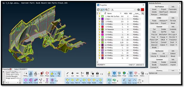
Step 4: Meshing and Assigning Thickness
- We first, setup the mesh parameters like min length, max length and target element length using mesh perimeters option under the utilities tab as shown in the image given below:
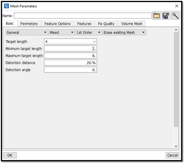
- After that we setup the quality criteria according to the given values in the aim of using quality criteria option under the utilities tab as shown in the image given below:
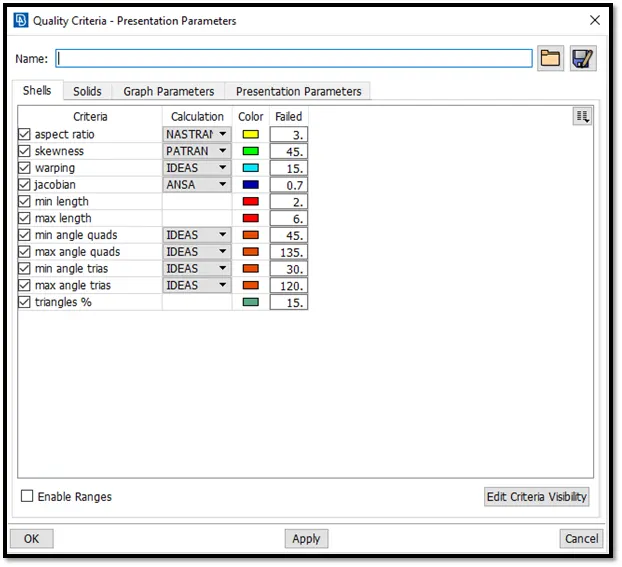
- In the 2-D meshing we will be considering only the above mid surfaced parts and we will be meshing it with mixed elements that include both quad and tria elements according the quality criteria given in the aim.
- We start 2D meshing of the component region by region so we can obtain a better mesh flow.
- We try to clear all the quality issues in the mesh to get a good error free mesh over mid surface of the component.
- We finally get to see the completely meshed model as shown in the image below:
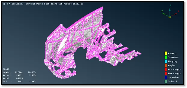
- We then assign thickness to the meshed component by ticking the checkbox called ‘Draw shell as solid’ present in presentation parameters of quality criteria under the utilities tab as shown in the image below:
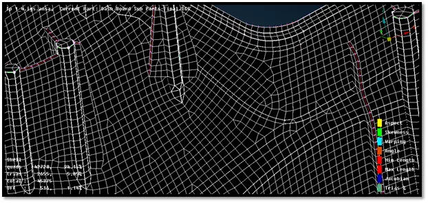
- We finally get the meshed model which is same as the parent geometry as their respective PID’s have the original thickness of the parent geometry as shown in the image below:
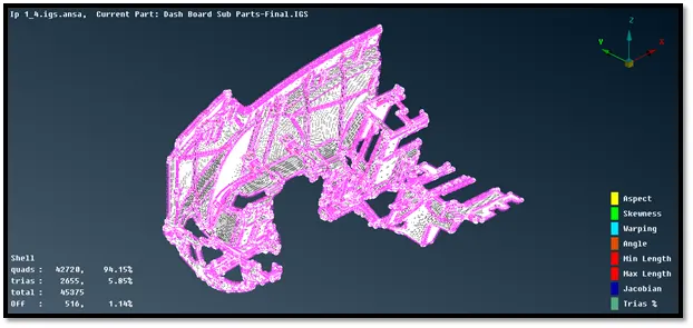
Conclusion:
- We have checked the given CAD geometry for the geometrical errors and rectified those using checks geometry
- We have generated mid surface from the parent geometry region by region so as to get a perfect mid-surface.
- We have performed 2D meshing over the mid surfaced geometry region by region and clearing all the quality errors to get a better mesh flow over the component.
- Finally, we have assigned thickness to the model which matches the parent geometry thickness.