Rear Suspension with Connections Project
Aim:
In this Project-2, ANSA pre-processor is used to generate mid surface, volume mesh. The quality criteria for some parts are different. Therefore, one should carefully apply them while meshing. Clear all off elements on surface mesh and then proceed to volume mesh. Understand about various connections used in rear suspension and deploy them accordingly.
Quality Criteria for Tria Elements (Tyre and Rim):
|
S.No |
Quality Criteria |
Value |
|
1 |
Target/Average length |
6.5 |
|
2 |
Minimum Length |
5 |
|
3 |
Maximum Length |
10 |
|
4 |
Skewness |
45 |
Quality criteria for Mixed elements (For Mid-surface only):
|
S.No |
Quality Criteria |
Value |
|
1 |
Target/Average length |
4 |
|
2 |
Minimum Length |
2 |
|
3 |
Maximum Length |
6 |
|
4 |
Aspect |
3 |
|
5 |
Warpage |
15 |
|
6 |
Skewness |
45 |
|
7 |
Jacobian |
0.7 |
|
8 |
Minimum Quad Angle |
45 |
|
9 |
Maximum Quad Angle |
135 |
|
10 |
Minimum Tria Angle |
30 |
|
11 |
Maximum Tria Angle |
120 |
Quality criteria for Tria (For other components):
|
S.No |
Quality Criteria |
Value |
|
1 |
Target/Average length |
4 |
|
2 |
Minimum Length |
2 |
|
3 |
Maximum Length |
6 |
|
4 |
Skewness |
45 |
Common Quality Criteria for Tetra elements are:
|
S.No |
Quality Criteria |
Value |
|
1 |
Tet-collapse |
0.2 |
Objective:
- Importing rear car suspension geometry into ANSA.
- Clean up the geometry until no topological error.
- Generate mid surface for required parts.
- Generate volume mesh for hollow parts.’
- Improve the mesh flow and solve off elements accordingly to given quality criteria.
- Give connections for rear suspension for NVH analysis.
Introduction:
Suspension has been an essential component for automobiles. The rear suspension of a vehicle performs the same general function as front suspension, but the specific construction is typically quite different. The ideal suspension for a vehicle depends a lot on the vehicle’s body style and performance requirements. The most basic purposes of a suspension system are to prevent the body of a vehicle from hitting the ground and to keep the tires in contact with the road.
Suspension systems are generally classified into dependent and independent systems. The wheels in a dependent system are perpendicular to the axle and parallel with each other. The most common suspension of this type is leaf-spring rear suspension, which consists of multiple metal bars, or leaves bound together. It is an older design but is still most common on trucks and other heavy vehicles.
Procedure:
Step 1: Importing geometry model
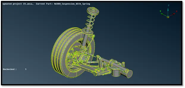
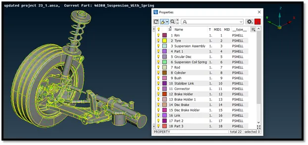
Import the geometry into ANSA and do topo to stich the surfaces. Isolate each part and set PID’s for the rear suspension assembly.
Step 2: Geometry clean-up
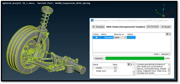
Clean the geometry using checks manager. Enable unchecked faces, collapsed cons, triple cons, needle faces, overlapped faces, cracks, single cons. Clear all these issues until no error is found. One can use fix option in ANSA to clear all the errors automatically.
However, sometimes manual intervention is required for fixing some errors. Manually we can use options like cut, release and delete for topo clean up.
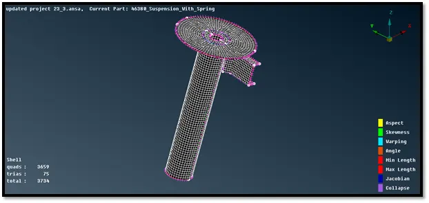
Step 3: Mid- Surface generation
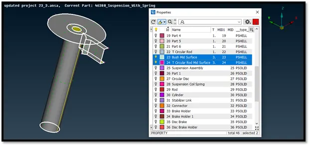
Two parts are having thickness less than 5 mm so we will do 2D meshing for those two parts.
By using offset we can easily generate mid surface mid surface for the geometry. As this sheet metal has thickness of 3 mm we can offset this with 1.5 mm for mid surface. Always enable cross-hatch feature and use feature area for easy selection. In the topo mode, we need to select the faces option ---> offset to extract the mid-surface.
Now we will switch to mesh mode and we need to give the shell element size length according to the given input = 4 mm. We will now feed the required values specified in the element quality criteria.
Average/target length is specified in the mesh parameters as well. For meshing spot mesh and best methods were used. Reconstructing was done to obtain a new mesh. Smooth was used to get a proper mesh flow.
The next keep parameter for better mesh flow is to avoid the opposite trias and trias which are present near the edges or holes or on the fillets. In order avoid these the commonly used commands are split and swap commands under the elements title and also join command under the macros title in the mesh mode.
Step 4: Volume mesh generation
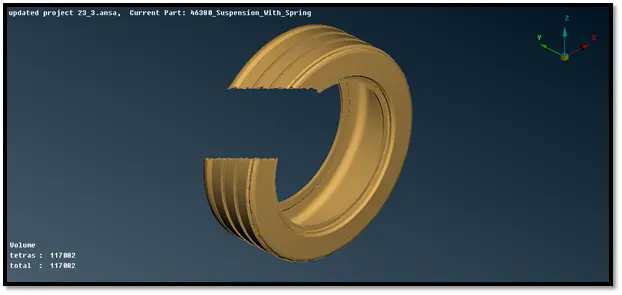
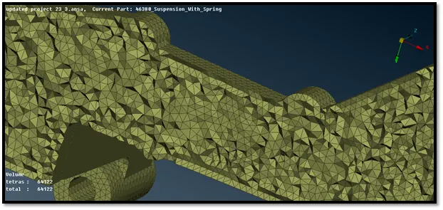
Initially, we will do surface meshing after which we will proceed for volume mesh generation.
The surface mesh generation can be done manually for accurate results and proper feature capturing. This process is similar to that 2D meshing and we will be using ortho tria for curved surfaces and normal tria for flat surfaces.
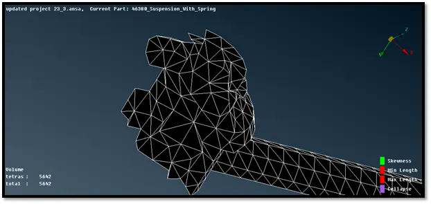
After meshing the geometry we check for the failed elements or off elements and remove them with the help of reconstruct, split or swap options.
Here we need to fix the kinks and raised edges since these elements will come out of the geometry and it will not be shown as failed elements or off elements.
Initially we will do surface mesh for Rim and Tyre separately because the quality parameters are different for these two components. And then we will do surface mesh for rest of the components and check for the quality parameters.
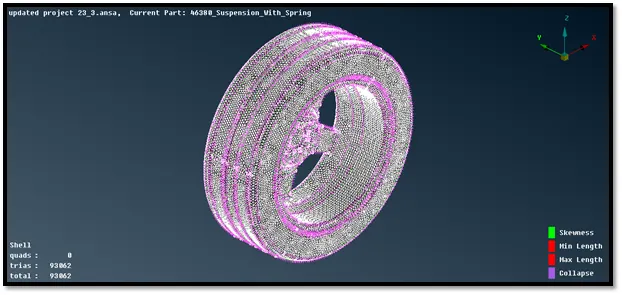
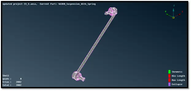
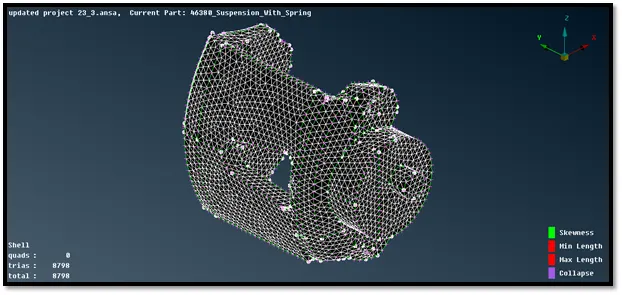
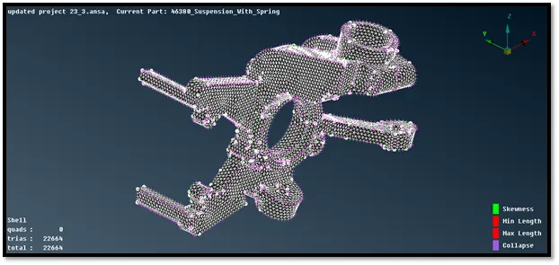
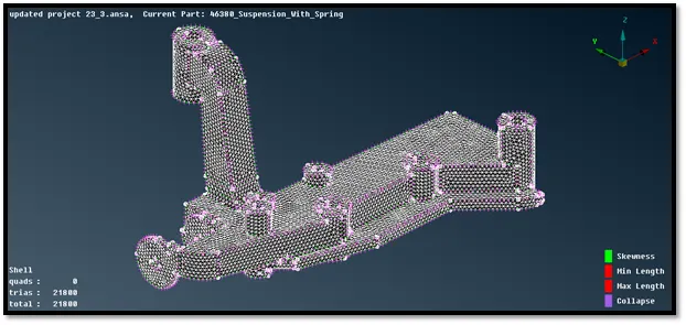
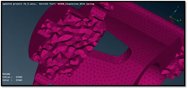
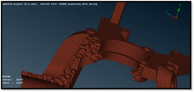
Now, under volume mesh module the volume of the given component is defined using tool volumes--->define--->manual option.
In order to volume mesh we need to define the geometry as closed volume. So, we will define under them difference property ids.
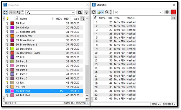
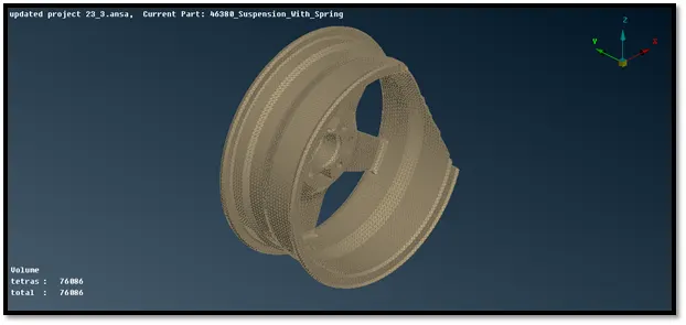
Now, we need to mesh the geometry with the help of tetra FEM and it will mesh the whole volume with tetra elements.
After complete volume mesh we check for tetcollapse.
Step 5: Connections
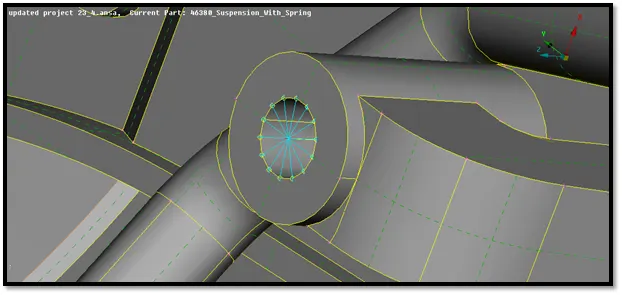
RBE2 Single Cluster Connections:
In this type of RBE2, we provide connection to two or more holes on two or more surfaces which nearer to each other and lock all their axes and degrees of freedom.
In order to implement this we should go to NASTRAN module and under elements tab we select the RBE2 option.
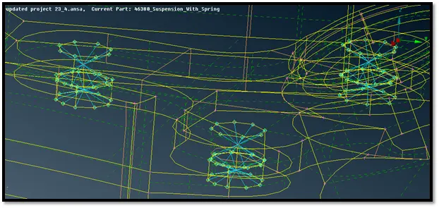
RBE2 Spider Connections:
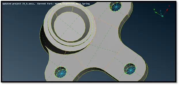
In this type of RBE2, we provide connection to one hole which is present on the model to make it rigid in all the axes which avoids movement of it. We should go to NASTRAN module and under elements tab we select the RBE2 option.
We provide these types of connections were there are independent holes present as shown in the figure below.
RBE2 Two Node Connections:
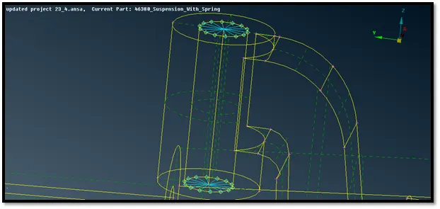
We should go to NASTRAN module and under elements tab we select the RBE2 option and under RBE2 we select the Two Node option and then we select the two required nodes to create a connection as shown in the figures below.
Bolt Connections:
In this type of connections, we provide connections to wherever the bolts are going to be fitted in the model.
We first create a 3D point near the holes of the bolt connection using the On COG option present in the Points tab of TOPO module. Then we convert the 3D points into bolt washer point using Convert option present in the Assembly tab.
After that, we go to the Connection Manager option present in the Assembly tab and select on the all washer points and then we press middle mouse button to get the connection manager tab.
We have 3 tabs in the connection manager menu namely connectivity list, connection list and FE representation settings.
We go to the connection list and we proceed to give connection for which all parts we want using F1 tab we go to the model and we select each and evert part and press enter to confirm since this model has a single PID we don’t need to go every time and select the parts, after confirming the connectivity list tab is also updated based on the connections given.
Finally, we got to the FE representation tab and under it we provide the FE representation type as Bolt and then we provide the zones to be attached as Inner so that all the zones inside the bolt connections get rigidly fixed. We apply all the settings and click on Realize option.
We, finally obtain the bolt connection in which all the nodes nearing to the boundary of the bolt connections are connected using RBE2 and there is a vertical connection between these connections.
Seam Weld Connections:
In this type of connections, we provide connections to wherever the welding operation is going to be performed in the component.
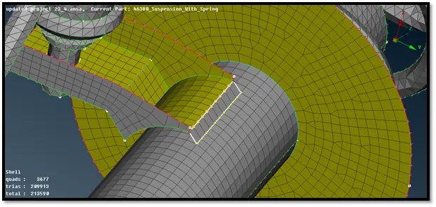
In this model, we create seam weld connections only. We first create a curve near the welding area using the Feat2Curve option present under the Perimeters of the Mesh module.
We then, use the Convert option present in the Assembly tab to convert to a Seam line. After that, we go to the Connection Manager option present in the Assembly tab and select on two parts which are to be welded to each other and then we press middle mouse button to get the connection manager tab.
We have 3 tabs in the connection manager menu namely connectivity list, connection list and FE representation settings. We go to the connection list and we proceed to give connection list and we proceed to give connection for which all parts we want using F1 tab we go to the model and we select each and every part and press enter to confirm.
Then we go to the FE representation tab and under it we provide the FE representation type as Y joint shell or Overlap shell according to our requirement, here we will use overlap shell since the parts to be welded are parallel to each other.
We provide the Search Distance and we provide the Base Sheet as P1, then we provide the width of the weld and representation type could be used for all the seam welds.
Finally, we press on Apply and we press on Realize. We see that we obtain a seam weld connection between two parts as shown in the image given below.
Step 6: Transform
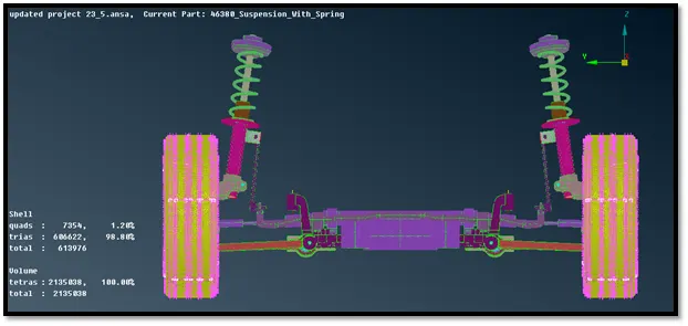
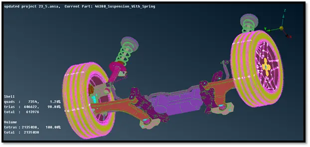
After completing surface mesh, volume mesh, mid surfacing and connections we have to use transform option in order to create exact mirror of the model on the other side.
Use transform and select all the entities including connections to generate exact replica of the model on the other side.
Now we use symmetry a mirror 3 points plane operation and select 3 points on the edge. These 3 points represent all the 3 coordinates (x, y, z). This helps all the entities to transform on the other side.
Conclusion:
In this project, I have generated mid surfaces and volume mesh using different options available in ANSA and had done topological clean up. I was able to achieve better mesh flow using smooth, reconstruct, swap, and move and paste options also eliminated kinks and raised edges. I have successfully applied different quality criteria and mesh parameters for different part and cleared off elements during mesh generation and also deployed connections for the rear suspension. Overall I have done pre-processing for rear suspension using ANSA.