Tetra Meshing for Rearview Mirror
Aim:
To obtain a 3D Tetra Mesh from the rear view mirror component and to check for geometrical errors and mesh with the given element Quality criteria.
|
S.No |
Quality Criteria |
Value |
|
1 |
Target/Average length |
1 |
|
2 |
Minimum Length |
0.5 |
|
3 |
Maximum Length |
2 |
|
4 |
Tetcollapse |
0.2 |
Procedure:
Geometry Clean-up:
- The rear view mirror model is imported into ANSA.
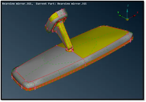
Fig: Imported geometry file
- Now, the topo is performed in order to get a refined geometry. Then we must assign the element size in general, under perimeters title ---> length ---> perimeters and macros as 1 mm in mesh mode for the whole model. We will also orient the model sets a uniform orientation direction to all visible faces according to the orientation of the majority of the faces, under faces title --->orient.
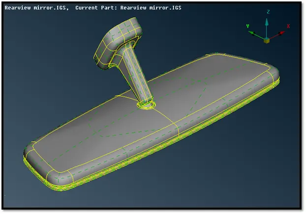
Fig: Refined geometry model
- After which we must do a check geometry for the model by selecting checks--->geometry in the tools bar and fix the errors shown. The various errors are displayed such as needle faces, unchecked faces, triple cons, etc. Auto fix option was opted for resolving these errors.
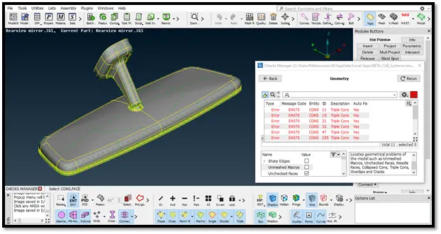
Fig: Applying geometry check
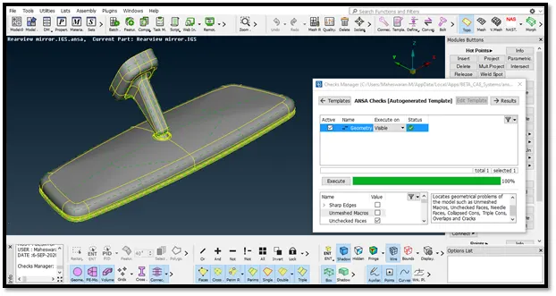
Fig: Using auto fix option
Meshing:
- Now, we will switch to mesh mode and we need to give the shell element size length according to the given input = 1 mm.
- We will now feed the required values specified in the element quality criteria. Average/target lengthis specified in the mesh parameters as well.
- After which we will select spot meshing and the surface of the geometry model is meshed using tria elements.
- We will be using ortho tria for curved surfaces and normal tria for flat surfaces.
- After meshing the geometry we check for the failed elements or off elements and remove them with the help of reconstruct, split or swap
- Here we need to fix the kinks and raised edges since these elements will come out of the geometry and it will not be shown as failed elements or off elements.
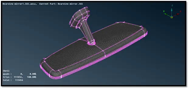
Fig: 2D Meshed geometry model
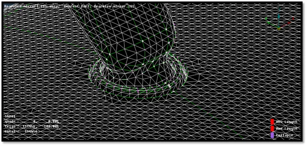
Fig: 2D Meshed geometry model
- Now, under volume mesh module the volume of the given component is defined using tool volumes--->define--->manual option.
- In order to volume mesh we need to define the geometry as closed volume. So, we will define under them difference property ids.
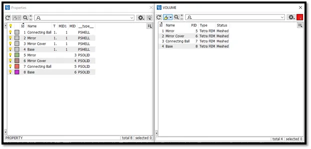
Fig: PID and Volumes
- Now, we need to mesh the geometry with the help of tetra FEM and it will mesh the whole volume with tetra elements.
- After complete volume mesh we check for tetcollapse.
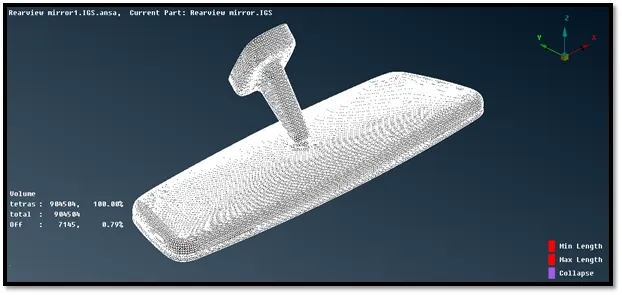
Fig: Finished model
Result:
The given rear view mirror model was meshed with the tria elements and the volume mesh was created and was checked for tetcollapse errors.
Google Drive Link for the Model:
https://drive.google.com/file/d/1WUNqGfEIHmWIKBVb78UbxIkvcmKSd7WJ/view?usp=sharing